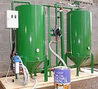
Processor - with pre-heat / drying tank
While processors systems can have several tanks, a system employing just two tanks has been developed by Goat Industries in the UK to try and eliminate as many hazards as possible.
Contents
- 1 Basic design
- 2 Operating procedure
- 2.1 State diagram for a processor with preheat/drying tank
- 2.2 Step 1. (Oil In)
- 2.3 Step 2. (Heat Oil)
- 2.4 Step 3. (Dry oil)
- 2.5 Step 4. (Add Methanol)
- 2.6 Step 5. (Add Catalyst)
- 2.7 Step 6. (Add oil to Methoxide)
- 2.8 Step 7. (Purge pipe work)
- 2.9 Step 8. (Drain glycerol)
- 2.10 Step 9. (Drain the glycerol)
- 2.11 Step 10. (Water wash)
- 2.12 Step 11. (Drain oil from heating/drying tank)
- 2.13 Step 12. (Transfer Biodiesel)
- 2.14 Step 13. (Heat Biodiesel)
- 2.15 Step 14. (Dry Biodiesel)
- 2.16 Step 15. (Pump out Biodiesel)
Basic design
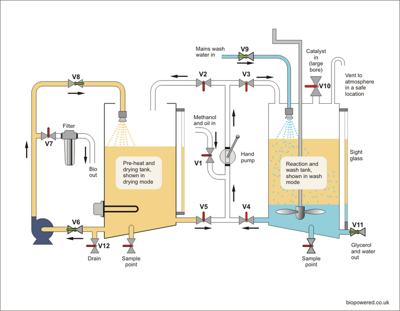
The design ensures that all the electrics and heaters are located in one tank, while the reaction with Methanol takes place in a second, separate tank. The temperatures required for biodiesel production of around 60°C presents no flammability or toxic risks in respect of vegetable oil or finished Biodiesel, provided the heating element is always submerged in liquid, so the oil is heated using an electrical heating element which is interlocked with a level switch in a dedicated tank.
The Methanol and catalyst is mixed to make Methoxide in the sealed reactor tank by a manually powered paddle arrangement. The preheated oil is then manually pumped into the Methoxide thus making it an AAF reaction.
As the design concept precludes the use of electrical power after the initial heating of the oil, water washing is used for final Methanol and soap removal after draining the Glycerol. Although not a flexible design in terms of recovering Methanol, it’s probably one of the safest. Once any soap, excess Methanol and catalyst have been removed in the wash water, the Biodiesel is pumped back to the first tank for spray drying.
It is important with this design that the height of the Methanol and oil inlet is above the maximum liquid level in both tanks, preferably above the tank tops, to prevent any back flow of liquids when the valves are operated.
The valve (V11) is used for draining both Glycerol and wash water. You should check with your local Water Authority, but wash water can normally be discharged to the sewer (not a surface water drain). However, Glycerol should be collected in a suitable container and disposed of in an appropriate manner. When draining Glycerol ensure that the work space is well ventilated and avoid breathing any fumes during the process.
Wetted components of the hand pump must be compatible with vegetable oil, Methanol and Biodiesel.
It is imperative that paddle arrangement is securely mounted at the top of the tank with a sealed, well lubricated bearing and that the bottom section is prevented from excess movement which might allow it to come in contact with the sides or bottom of the tank.
Operating procedure
State diagram for a processor with preheat/drying tank
This table tells you about the status of each valve, the heater and pumps at various stages of the process.
State diagram: Green = valve open, pump running or heater on.
| Step | Heater | Hand Pump |
Elect. Pump |
V1 | V2 | V3 | V4 | V5 | V6 | V7 | V8 | V9 | V10 | V11 | V12 | Notes |
| Oil in | Pre-filtered. | |||||||||||||||
| Heat oil | 80°C | If the oil requires drying, step 3 can commence at 40°C. | ||||||||||||||
| Dry oil | 80°C | Dry until hot pan test gives a pass. | ||||||||||||||
| Add Methanol | V1 | Disconnect electrics. | ||||||||||||||
| Add Catalyst | Close V10 immediately after introduction of catalyst and thoroughly mix with paddle. | |||||||||||||||
| Add oil to Methoxide | Slowly introduce oil to Methoxide whilst mixing with the paddle. Ensure temperature does not exceed 50°C. | |||||||||||||||
| Purge pipe work | To remove ant traces of Methanol or Methoxide from interconnecting pipe work. | |||||||||||||||
| Drain glycerol | Query acid wash as next step? | |||||||||||||||
| Water wash | Adj. | Adj. | Balance valves V9 and V11 to ensure a constant water level without Biodiesel running out of V11 or the tank overfilling in which case biodiesel will be forced out of the vent. | |||||||||||||
| Drain oil from heating/drying | Drain as well as possible to avoid contaminating the Biodiesel. | |||||||||||||||
| Transfer Biodiesel | ||||||||||||||||
| Heat Biodiesel | 60°C | Adj. | When up to temperature drain any water which has dropped out of the Biodiesel. | |||||||||||||
| Dry Biodiesel | Until sample remains clear at room temperature. | |||||||||||||||
| Pump out Biodiesel | Pump into vehicle tank or suitable storage. |
Step 1. (Oil In)
Step 2. (Heat Oil)
Step 3. (Dry oil)
Step 4. (Add Methanol)
Step 5. (Add Catalyst)
Step 6. (Add oil to Methoxide)
Step 7. (Purge pipe work)
Step 8. (Drain glycerol)
Step 9. (Drain the glycerol)
Step 10. (Water wash)
Step 11. (Drain oil from heating/drying tank)
Step 12. (Transfer Biodiesel)
Step 13. (Heat Biodiesel)
Step 14. (Dry Biodiesel)
Step 15. (Pump out Biodiesel)
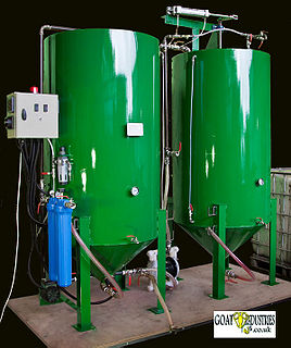
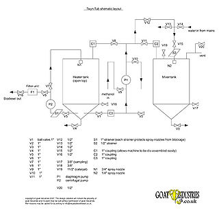
The Twyn Tub or 'TT' range of processors are an industrial type of design that produces biodiesel to the European standard, EN14214. The process starts off in the left hand tank, that has heating elements inserted and the main reaction takes place in the right hand tank, which is compltely free of any electrical items. The plant was designed to be as safe as reasonly possible without using extortionately expensive components and isolating the reaction stage of the process was found to be the most cost effective way of doing this.
- TT700A
In the photo above, it can be seen that an air operated main pump and mixing ram is used ,whilst smaller models can be hand operated. The left hand heating tank is open at the top and has a high quality level sensor built into it's side to ensure that the heater elements are not turned on accidentally. Most accidents in making biodiesel have been caused this way, especially if the plant design allows methanol vapour to be present at any time in the heating tank during the process. This design does not allow this to happen.
The plant has a large number of valves, inlets and outlets to enable the pumps to work in a large number of different permutations, making the plant as a whole extremely flexible. A separate, electric pump, is used on the left hand side to avoid contamination of the final product with fluids in the main air operated pump. The process uses water to purify the biodiesel, with spray nozzles for washing and drying. No ionic exchange resins are used as these turn the soaps back to acids which are corrosive to vehicle engine parts.


