Difference between revisions of "Pump - Leo XKM60"
| (4 intermediate revisions by one other user not shown) | |||
| Line 1: | Line 1: | ||
<metadesc>Leo XKM60, Biodiesel processor pump, Biodiesel transfer pump, WVO pump, WVO transfer pump, Leo XKM60 performance curve</metadesc> | <metadesc>Leo XKM60, Biodiesel processor pump, Biodiesel transfer pump, WVO pump, WVO transfer pump, Leo XKM60 performance curve</metadesc> | ||
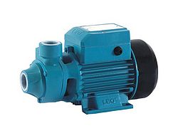
[[File: Leo XKM60.jpg|250px|thumb|Leo XKM60 pump.]] | [[File: Leo XKM60.jpg|250px|thumb|Leo XKM60 pump.]] | ||
| − | The Leo XKM60 is probably the second most popular processor pump in the UK, second only to the [[TAM105]]. | + | The Leo XKM60 is a periferal turbine pump and is probably the second most popular processor pump in the UK, second only to the [[TAM105]]. |
| − | It is sold as a clear water pump with a maximum temperature rating of 60°C, but it has been found by many home brewers to operate quite satisfactorily at temperatures up to 80°C and above, pumping oil and | + | It is sold as a clear water pump with a maximum temperature rating of 60°C, but it has been found by many home brewers to operate quite satisfactorily at temperatures up to 80°C and above, pumping oil and biodiesel. |
It is not self priming, but once primed has a very respectable suction lift for a pump of its size and can be used for transferring and filtering vegetable oil, provided the oil has a low viscosity. | It is not self priming, but once primed has a very respectable suction lift for a pump of its size and can be used for transferring and filtering vegetable oil, provided the oil has a low viscosity. | ||
| Line 30: | Line 30: | ||
[[File:Leo XKM 60 curve.png]] | [[File:Leo XKM 60 curve.png]] | ||
| + | |||
| + | |||
| + | |||
| + | |||
| + | <gallery caption="Leo XKM60 mechanical seal replacement" widths="280px" heights="200px" perrow="3" align="center"> | ||
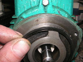
| + | File:Leo XKM60 3 screws.JPG|The body is removed by undoing three screws. | ||
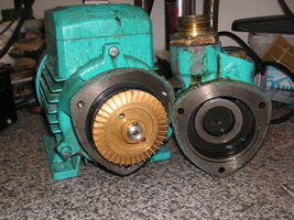
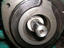
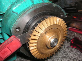
| + | File:Leo XKM60 cover off.JPG|Removing the body reveals the impeller. The impeller is a friction fit on the shaft and is fitted with a round ended parallel key. | ||
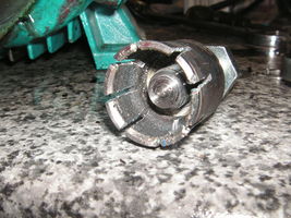
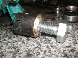
| + | File:Leo XKM60 puller 1.JPG|The impeller material appears to be quite soft, so levering it off the shaft is not recommended. This simple puller was made to engage with the groove on the impeller boss. | ||
| + | File:Leo XKM60 puller 2.JPG|Another view of the puller. | ||
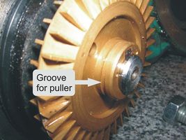
| + | File:Leo XKM60 groove for puller.jpg|The puller engages with this groove. The impeller is not a very tight fit on the shaft. The writer didn't, but would in retrospect, recommend using feeler gauges to measure the clearance between the lantern ring and the impeller before removing it. By measuring other components a figure of 0.02mm was arrived at later, but measuring before removal would have been a wise move. | ||
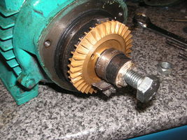
| + | File:Leo XKM60 puller in position.JPG|The fingers of the puller are clamped into the groove by tightening a hose clip around it. | ||
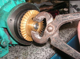
| + | File:Leo XKM60 alternative puller.JPG|This method wasn't tried but in the absence of facilities to make the puller, pincers could be attached and very gently tapped with a light hammer. | ||
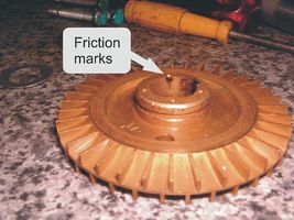
| + | File:Leo XKM60 friction marks.jpg|Once removed, friction marks can be seen on the inside of the impeller boss. The boss is slightly distorted by being centre punched at four points and it's simply the friction caused by the punch marks which holds the impeller laterally on the shaft. | ||
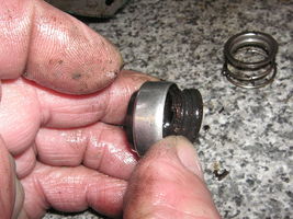
| + | File:Leo XKM60 circlip.JPG|The rotating section of the mechanical seal is held to the shaft by a circlip and washer. Removing the circlip and washer allows the seal to be slid off the shaft. Care is needed when removing this item as excessive force will pull the steel washer off the rubber bellows. | ||
| + | File:Leo XKM60 seal damage.JPG|The damage to this seal was a split in the bellows. | ||
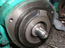
| + | File:Leo XKM60 static ceramic disc.JPG|As the damage was only to the bellows and the static ceramic disc was quite serviceable, it was not replaced. If replacement is needed, the three screws holding the lantern ring to the motor should be removed and a puller used to remove the lantern ring from the shaft. The front motor bearing will come away with the lantern ring and need to be removed to allow access to the back of the static ceramic disc. It should then be possible to gently drift out the old disc and install the replacement. The static ceramic disc is fitted with a peripheral rubber seal which fits in the housing in the lantern ring. | ||
| + | File:Leo XKM60 casing seal.JPG|While disassembled, check the body to lantern ring seal. This is a square section seal but if damaged could be replaced by a suitably sized "O" ring. | ||
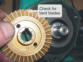
| + | File:Leo XKM60 bent blade.jpg|Also check for bent or damaged blades. | ||
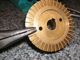
| + | File:Leo XKM60 straightening blade.JPG|The impeller material is sufficiently soft to allow bent blades to be straightened by simply squeezing between the jaws of long nosed pliers. | ||
| + | File:Leo XKM60 feeler gauge.JPG|Reassembly is a simple matter BUT, it's imperative the impeller is positioned correctly on the shaft. Being a peripheral turbine pump the clearances between the impeller, the lantern ring and the body are critical. If wrong, the impeller will rub and may be damaged. The most accurate measurement which could be obtained reviled that a 0.2mm (8 thou imperial) gap is required between the impeller and the lantern ring. This can be set using feeler gauges. Gently tap the impeller onto the shaft using a tubular drift until friction is felt on the feeler gauge. Finish reassembling the pump and, using a screwdriver through the cooing fan cowl, spin the pump manually. Check for scraping noises and adjust the position of the impeller if necessary. Before putting back into service give the pump a quick spin by powering up the motor and again listen for any interference. | ||
| + | |||
| + | </gallery> | ||
| + | |||
| + | |||
| + | |||
| + | |||
[[User:Bio-rich-time-poor|Bio-rich-time-poor]] 12:12, 7 January 2011 (UTC) | [[User:Bio-rich-time-poor|Bio-rich-time-poor]] 12:12, 7 January 2011 (UTC) | ||
Latest revision as of 21:05, 3 March 2013
The Leo XKM60 is a periferal turbine pump and is probably the second most popular processor pump in the UK, second only to the TAM105.
It is sold as a clear water pump with a maximum temperature rating of 60°C, but it has been found by many home brewers to operate quite satisfactorily at temperatures up to 80°C and above, pumping oil and biodiesel.
It is not self priming, but once primed has a very respectable suction lift for a pump of its size and can be used for transferring and filtering vegetable oil, provided the oil has a low viscosity.
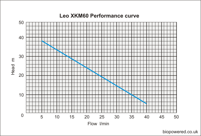
The Leo XKM60 has the following specifications and performance:
- power(HP) … 0.5
- power(kw) ... 0.37
- Max. head ... 40m
- Max. flow ... 40L/min
- Max. SUCT ... 8m
- Inlet/Outlet connections … 1” BSP, female
- Body material ... Cast iron
- Impeller material ... Brass
- Leo XKM60 mechanical seal replacement
The puller engages with this groove. The impeller is not a very tight fit on the shaft. The writer didn't, but would in retrospect, recommend using feeler gauges to measure the clearance between the lantern ring and the impeller before removing it. By measuring other components a figure of 0.02mm was arrived at later, but measuring before removal would have been a wise move.
As the damage was only to the bellows and the static ceramic disc was quite serviceable, it was not replaced. If replacement is needed, the three screws holding the lantern ring to the motor should be removed and a puller used to remove the lantern ring from the shaft. The front motor bearing will come away with the lantern ring and need to be removed to allow access to the back of the static ceramic disc. It should then be possible to gently drift out the old disc and install the replacement. The static ceramic disc is fitted with a peripheral rubber seal which fits in the housing in the lantern ring.
Reassembly is a simple matter BUT, it's imperative the impeller is positioned correctly on the shaft. Being a peripheral turbine pump the clearances between the impeller, the lantern ring and the body are critical. If wrong, the impeller will rub and may be damaged. The most accurate measurement which could be obtained reviled that a 0.2mm (8 thou imperial) gap is required between the impeller and the lantern ring. This can be set using feeler gauges. Gently tap the impeller onto the shaft using a tubular drift until friction is felt on the feeler gauge. Finish reassembling the pump and, using a screwdriver through the cooing fan cowl, spin the pump manually. Check for scraping noises and adjust the position of the impeller if necessary. Before putting back into service give the pump a quick spin by powering up the motor and again listen for any interference.
Bio-rich-time-poor 12:12, 7 January 2011 (UTC)
