Uncategorised files
Showing below up to 50 results in range #201 to #250.
View (previous 50 | next 50) (20 | 50 | 100 | 250 | 500)
 File out.JPG 2,048 × 1,536; 759 KB
 File out.jpg 2,048 × 1,536; 677 KB
 Fill level weld.JPG 2,048 × 1,536; 701 KB
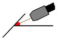 Fillet Joint.jpg 307 × 211; 6 KB
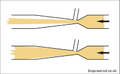 Fillingventuri.png 400 × 247; 14 KB
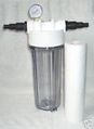
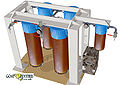
 Filter-set.jpg 653 × 490; 63 KB
 Filter.jpg 102 × 140; 4 KB
 Filter bits.jpg 2,155 × 1,701; 1.29 MB
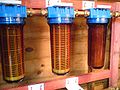
 Filterfarm1.jpg 348 × 280; 17 KB
 Filtside.jpg 210 × 350; 26 KB
 Final valve layout 1.jpg 3,648 × 2,736; 810 KB
 Final valve layout 2.jpg 3,648 × 2,736; 721 KB
 First whole batch HMPE.JPG 2,048 × 1,536; 635 KB
 Fittings1.jpg 3,648 × 2,736; 381 KB
 Fittings2.jpg 3,648 × 2,736; 400 KB
 Fittings3.jpg 3,648 × 2,736; 411 KB
 Fittings4.jpg 3,648 × 2,736; 291 KB
 Fittings5.jpg 3,648 × 2,736; 408 KB
 Fittings6.jpg 3,648 × 2,736; 395 KB
 Fittings7.jpg 3,648 × 2,736; 426 KB
 Flange silver soldered to fitting.JPG 2,048 × 1,536; 740 KB
 Flex brackets.JPG 2,048 × 1,536; 741 KB
 Float switch.jpg 3,648 × 2,736; 728 KB
 Float switch 001.jpg 2,736 × 3,648; 892 KB
 Float switch circuit.png 763 × 383; 16 KB
 Flux liquefies and runs.JPG 2,048 × 1,536; 722 KB
 Flux mixed into paste and applied to joint.JPG 2,048 × 1,536; 712 KB
 Flying hose holder 1.JPG 1,536 × 2,048; 642 KB
 Flying hose holder 2.JPG 2,048 × 1,536; 729 KB
 Flying hose holder 3.JPG 2,048 × 1,536; 708 KB
 Foot.JPG 2,048 × 1,536; 736 KB
 Foot strainer 1.JPG 2,048 × 1,536; 723 KB
 Foot strainer 2.JPG 2,048 × 1,536; 714 KB
 Foot strainer 3.JPG 2,048 × 1,536; 727 KB
 Fphe.jpg 320 × 240; 12 KB
 Fridge switch.PNG 202 × 190; 104 KB
 Fueling tank.jpg 331 × 495; 32 KB
 Fuel production record.xls ; 58 KB
 Fuge fan cover.jpg 1,362 × 617; 76 KB
 Full view 1.jpg 1,765 × 1,250; 250 KB
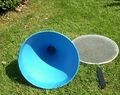
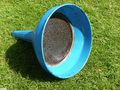 Funnel filter.jpg 3,648 × 2,736; 1.86 MB
- GLStatediagraminMSword.doc ; 64 KB
 GL hand beaten venturi 1.gif 384 × 216; 54 KB
 GL hand beaten venturi 2.gif 479 × 421; 104 KB
 GL hand beaten venturi 3.gif 464 × 478; 190 KB
- GL processor schematic.cdr ; 28 KB
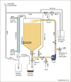 GL processor with valve to allow use of sight tube.png 600 × 693; 69 KB
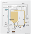 GL processor with valve to allow use of sight tube and SHHE.png 600 × 663; 98 KB
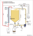 GL processor with vent path in red.png 823 × 910; 47 KB
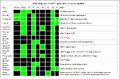 GL state diagram.jpg 1,125 × 745; 154 KB


