Difference between revisions of "Thermocouples"
(→Screwed connection) |
|||
| (32 intermediate revisions by 3 users not shown) | |||
| Line 1: | Line 1: | ||
| − | |||
[[File:TCprincipals.png|400px|thumb|right|Basic development of thermocouple theory]] | [[File:TCprincipals.png|400px|thumb|right|Basic development of thermocouple theory]] | ||
| − | A thermocouple is a | + | A thermocouple is a device which comprises two conductors made from dissimilar metals. These generate a very small voltage known as contact potential. The voltage generated varies with temperature. They are available in a variety of types dependent on conductor material. Each combination of conductor material has a different temperature range and output voltage. Thermocouples are available mounted in various housings to suit specific applications. |
__TOC__ | __TOC__ | ||
| Line 11: | Line 10: | ||
In the early part of the ninetieth century Thomas Seebeck, an Estonian-born German physicist, discovered that in a circuit made with two dissimilar conductor materials, a voltage would be generated whenever there was a difference in temperature between the two junctions. | In the early part of the ninetieth century Thomas Seebeck, an Estonian-born German physicist, discovered that in a circuit made with two dissimilar conductor materials, a voltage would be generated whenever there was a difference in temperature between the two junctions. | ||
| − | In the top diagram, | + | In the top diagram, right, a voltage will be generated if the right-hand junction is heated. The voltage will be proportional to the temperature, so the hotter the junction the higher the voltage. It’s not quite a linear relationship, but very close. If the voltage were measured and converted to a temperature, the figure arrived at won’t be the actual temperature, it will be the difference in temperature between the hot and the cold junction. So if the cold junction is at an ambient of 22°C and the hot junction at 100°C then the voltage reading will correspond to 78°C. |
| − | To make | + | To make Seebeck’s discovery more practical, the cold junction needs to be at a known temperature. Looking at the centre diagram, using 0°C as a reference for the cold junction means that the temperature corresponding to the voltage generated by the hot junction will be an absolute measurement. |
Rather than having bowls of ice water slopping around all over the place, modern instruments contain electronics to replicate the cold junction which makes life a whole lot less complicated as shown in the lower diagram. Whilst the built in cold junction compensation makes life easer in some respects, it makes it a little more complicated in others. You will notice that the system using the water bath uses copper wires to connect to the volt meter. This is normally bad practice when connecting thermocouples as again you have a junction of dissimilar metals which will also generate a voltage if their temperature differs. | Rather than having bowls of ice water slopping around all over the place, modern instruments contain electronics to replicate the cold junction which makes life a whole lot less complicated as shown in the lower diagram. Whilst the built in cold junction compensation makes life easer in some respects, it makes it a little more complicated in others. You will notice that the system using the water bath uses copper wires to connect to the volt meter. This is normally bad practice when connecting thermocouples as again you have a junction of dissimilar metals which will also generate a voltage if their temperature differs. | ||
In the centre diagram the use of copper wires is possible because both cold junctions are at the same temperature in the water bath. Where the cold junction compensation is located in the instrument it is necessary to use the same, or very similar, conductor materials for the wiring between the thermocouple and the instrument. | In the centre diagram the use of copper wires is possible because both cold junctions are at the same temperature in the water bath. Where the cold junction compensation is located in the instrument it is necessary to use the same, or very similar, conductor materials for the wiring between the thermocouple and the instrument. | ||
| + | |||
| + | To this end you will find that two types of thermocouple wire are available, thermocouple wire and thermocouple extension wire or cable. | ||
| + | |||
| + | The former is wire manufactured from the materials designated for that particular type of thermocouple, which, in the case of a K type thermocouple is chromel (comprising 90% nickel and 10% chromium) and alumel (comprising 95% nickel, 2% manganese, 2% aluminium and 1% silicon) | ||
| + | |||
| + | The latter is manufactured from cheaper alloys, typically copper/constantan for a K type thermocouple, and cannot be used to manufacture thermocouples. | ||
==Thermocouple types== | ==Thermocouple types== | ||
| + | [[File:Thermocouples colours.png|400px|thumb|right|Thermocouple wire colours]] | ||
| − | |||
| + | |||
| + | |||
| + | Almost any two metals can generate a contact potential, but specific combinations have become standard and are designed to suit different applications. | ||
| + | |||
| + | |||
| + | <table class=MsoNormalTable border=1 cellpadding=0 width=544 style="background-color:#F9F9F9" width:408.0pt; | ||
| + | mso-cellspacing:1.5pt;margin-left:12.0pt'> | ||
| + | <tr style='mso-yfti-irow:0;mso-yfti-firstrow:yes'> | ||
| + | <td style='padding:.75pt .75pt .75pt .75pt'> | ||
| + | <p class=MsoNormal align=center style='text-align:center'><span | ||
| + | style='font-size:10.0pt;font-family:Arial;color:black;mso-ansi-language:EN-US'>Type</span></p> | ||
| + | </td> | ||
| + | <td style='padding:.75pt .75pt .75pt .75pt'> | ||
| + | <p class=MsoNormal align=center style='text-align:center'><span | ||
| + | style='font-size:10.0pt;font-family:Arial;color:black;mso-ansi-language:EN-US'>Conductor | ||
| + | materials</span></p> | ||
| + | </td> | ||
| + | <td style='padding:.75pt .75pt .75pt .75pt'> | ||
| + | <p class=MsoNormal align=center style='text-align:center'><span | ||
| + | style='font-size:10.0pt;font-family:Arial;color:black;mso-ansi-language:EN-US'>Range | ||
| + | °C <br> | ||
| + | continuous</span></p> | ||
| + | </td> | ||
| + | <td width=85 style='width:63.75pt;padding:.75pt .75pt .75pt .75pt'> | ||
| + | <p class=MsoNormal align=center style='text-align:center'><span | ||
| + | style='font-size:10.0pt;font-family:Arial;color:black;mso-ansi-language:EN-US'>Output | ||
| + | µV/°C</span></p> | ||
| + | </td> | ||
| + | </tr> | ||
| + | <tr style='mso-yfti-irow:1'> | ||
| + | <td style='padding:.75pt .75pt .75pt .75pt'> | ||
| + | <p class=MsoNormal align=center style='text-align:center'><span | ||
| + | style='font-size:10.0pt;font-family:Arial;color:black;mso-ansi-language:EN-US'>E</span></p> | ||
| + | </td> | ||
| + | <td style='padding:.75pt .75pt .75pt .75pt'> | ||
| + | <p class=MsoNormal align=center style='text-align:center'><span class=SpellE><span | ||
| + | style='font-size:10.0pt;font-family:Arial;color:black;mso-ansi-language:EN-US'>chromel</span></span><span | ||
| + | style='font-size:10.0pt;font-family:Arial;color:black;mso-ansi-language:EN-US'>/constantan</span></p> | ||
| + | </td> | ||
| + | <td style='padding:.75pt .75pt .75pt .75pt'> | ||
| + | <p class=MsoNormal align=center style='text-align:center'><span | ||
| + | style='font-size:10.0pt;font-family:Arial;color:black;mso-ansi-language:EN-US'>0~1000</span></p> | ||
| + | </td> | ||
| + | <td width=85 style='width:63.75pt;padding:.75pt .75pt .75pt .75pt'> | ||
| + | <p class=MsoNormal align=center style='text-align:center'><span | ||
| + | style='font-size:10.0pt;font-family:Arial;color:black;mso-ansi-language:EN-US'>56</span></p> | ||
| + | </td> | ||
| + | </tr> | ||
| + | <tr style='mso-yfti-irow:2'> | ||
| + | <td style='padding:.75pt .75pt .75pt .75pt'> | ||
| + | <p class=MsoNormal align=center style='text-align:center'><span | ||
| + | style='font-size:10.0pt;font-family:Arial;color:black;mso-ansi-language:EN-US'>J</span></p> | ||
| + | </td> | ||
| + | <td style='padding:.75pt .75pt .75pt .75pt'> | ||
| + | <p class=MsoNormal align=center style='text-align:center'><span | ||
| + | style='font-size:10.0pt;font-family:Arial;color:black;mso-ansi-language:EN-US'>iron/constantan</span></p> | ||
| + | </td> | ||
| + | <td style='padding:.75pt .75pt .75pt .75pt'> | ||
| + | <p class=MsoNormal align=center style='text-align:center'><span | ||
| + | style='font-size:10.0pt;font-family:Arial;color:black;mso-ansi-language:EN-US'>0~700</span></p> | ||
| + | </td> | ||
| + | <td width=85 style='width:63.75pt;padding:.75pt .75pt .75pt .75pt'> | ||
| + | <p class=MsoNormal align=center style='text-align:center'><span | ||
| + | style='font-size:10.0pt;font-family:Arial;color:black;mso-ansi-language:EN-US'>52</span></p> | ||
| + | </td> | ||
| + | </tr> | ||
| + | <tr style='mso-yfti-irow:3'> | ||
| + | <td style='padding:.75pt .75pt .75pt .75pt'> | ||
| + | <p class=MsoNormal align=center style='text-align:center'><span | ||
| + | style='font-size:10.0pt;font-family:Arial;color:black;mso-ansi-language:EN-US'>K</span></p> | ||
| + | </td> | ||
| + | <td style='padding:.75pt .75pt .75pt .75pt'> | ||
| + | <p class=MsoNormal align=center style='text-align:center'><span class=SpellE><span | ||
| + | style='font-size:10.0pt;font-family:Arial;color:black;mso-ansi-language:EN-US'>chromel/alumel</span></span><span | ||
| + | style='font-size:10.0pt;font-family:Arial;color:black;mso-ansi-language:EN-US'></span></p> | ||
| + | </td> | ||
| + | <td style='padding:.75pt .75pt .75pt .75pt'> | ||
| + | <p class=MsoNormal align=center style='text-align:center'><span | ||
| + | style='font-size:10.0pt;font-family:Arial;color:black;mso-ansi-language:EN-US'>0~1100</span></p> | ||
| + | </td> | ||
| + | <td width=85 style='width:63.75pt;padding:.75pt .75pt .75pt .75pt'> | ||
| + | <p class=MsoNormal align=center style='text-align:center'><span | ||
| + | style='font-size:10.0pt;font-family:Arial;color:black;mso-ansi-language:EN-US'>40</span></p> | ||
| + | </td> | ||
| + | </tr> | ||
| + | <tr style='mso-yfti-irow:4'> | ||
| + | <td style='padding:.75pt .75pt .75pt .75pt'> | ||
| + | <p class=MsoNormal align=center style='text-align:center'><span | ||
| + | style='font-size:10.0pt;font-family:Arial;color:black;mso-ansi-language:EN-US'>N</span></p> | ||
| + | </td> | ||
| + | <td style='padding:.75pt .75pt .75pt .75pt'> | ||
| + | <p class=MsoNormal align=center style='text-align:center'><span class=SpellE><span | ||
| + | style='font-size:10.0pt;font-family:Arial;color:black;mso-ansi-language:EN-US'>nicrosil/nisil</span></span><span | ||
| + | style='font-size:10.0pt;font-family:Arial;color:black;mso-ansi-language:EN-US'></span></p> | ||
| + | </td> | ||
| + | <td style='padding:.75pt .75pt .75pt .75pt'> | ||
| + | <p class=MsoNormal align=center style='text-align:center'><span | ||
| + | style='font-size:10.0pt;font-family:Arial;color:black;mso-ansi-language:EN-US'>0~1100</span></p> | ||
| + | </td> | ||
| + | <td width=85 style='width:63.75pt;padding:.75pt .75pt .75pt .75pt'> | ||
| + | <p class=MsoNormal align=center style='text-align:center'><span | ||
| + | style='font-size:10.0pt;font-family:Arial;color:black;mso-ansi-language:EN-US'>38</span></p> | ||
| + | </td> | ||
| + | </tr> | ||
| + | <tr style='mso-yfti-irow:5'> | ||
| + | <td style='padding:.75pt .75pt .75pt .75pt'> | ||
| + | <p class=MsoNormal align=center style='text-align:center'><span | ||
| + | style='font-size:10.0pt;font-family:Arial;color:black;mso-ansi-language:EN-US'>R</span></p> | ||
| + | </td> | ||
| + | <td style='padding:.75pt .75pt .75pt .75pt'> | ||
| + | <p class=MsoNormal align=center style='text-align:center'><span | ||
| + | style='font-size:10.0pt;font-family:Arial;color:black;mso-ansi-language:EN-US'>platinum/PtRh13%</span></p> | ||
| + | </td> | ||
| + | <td style='padding:.75pt .75pt .75pt .75pt'> | ||
| + | <p class=MsoNormal align=center style='text-align:center'><span | ||
| + | style='font-size:10.0pt;font-family:Arial;color:black;mso-ansi-language:EN-US'>0~1600</span></p> | ||
| + | </td> | ||
| + | <td width=85 style='width:63.75pt;padding:.75pt .75pt .75pt .75pt'> | ||
| + | <p class=MsoNormal align=center style='text-align:center'><span | ||
| + | style='font-size:10.0pt;font-family:Arial;color:black;mso-ansi-language:EN-US'>10</span></p> | ||
| + | </td> | ||
| + | </tr> | ||
| + | <tr style='mso-yfti-irow:6'> | ||
| + | <td style='padding:.75pt .75pt .75pt .75pt'> | ||
| + | <p class=MsoNormal align=center style='text-align:center'><span | ||
| + | style='font-size:10.0pt;font-family:Arial;color:black;mso-ansi-language:EN-US'>S</span></p> | ||
| + | </td> | ||
| + | <td style='padding:.75pt .75pt .75pt .75pt'> | ||
| + | <p class=MsoNormal align=center style='text-align:center'><span | ||
| + | style='font-size:10.0pt;font-family:Arial;color:black;mso-ansi-language:EN-US'>platinum/PtRh10%</span></p> | ||
| + | </td> | ||
| + | <td style='padding:.75pt .75pt .75pt .75pt'> | ||
| + | <p class=MsoNormal align=center style='text-align:center'><span | ||
| + | style='font-size:10.0pt;font-family:Arial;color:black;mso-ansi-language:EN-US'>0~1600</span></p> | ||
| + | </td> | ||
| + | <td width=85 style='width:63.75pt;padding:.75pt .75pt .75pt .75pt'> | ||
| + | <p class=MsoNormal align=center style='text-align:center'><span | ||
| + | style='font-size:10.0pt;font-family:Arial;color:black;mso-ansi-language:EN-US'>10</span></p> | ||
| + | </td> | ||
| + | </tr> | ||
| + | <tr style='mso-yfti-irow:7;mso-yfti-lastrow:yes'> | ||
| + | <td style='padding:.75pt .75pt .75pt .75pt'> | ||
| + | <p class=MsoNormal align=center style='text-align:center'><span | ||
| + | style='font-size:10.0pt;font-family:Arial;color:black;mso-ansi-language:EN-US'>T</span></p> | ||
| + | </td> | ||
| + | <td style='padding:.75pt .75pt .75pt .75pt'> | ||
| + | <p class=MsoNormal align=center style='text-align:center'><span | ||
| + | style='font-size:10.0pt;font-family:Arial;color:black;mso-ansi-language:EN-US'>copper/constantan</span></p> | ||
| + | </td> | ||
| + | <td style='padding:.75pt .75pt .75pt .75pt'> | ||
| + | <p class=MsoNormal align=center style='text-align:center'><span | ||
| + | style='font-size:10.0pt;font-family:Arial;color:black;mso-ansi-language:EN-US'>-185~300</span></p> | ||
| + | </td> | ||
| + | <td width=85 style='width:63.75pt;padding:.75pt .75pt .75pt .75pt'> | ||
| + | <p class=MsoNormal align=center style='text-align:center'><span | ||
| + | style='font-size:10.0pt;font-family:Arial;color:black;mso-ansi-language:EN-US'>38</span></p> | ||
| + | </td> | ||
| + | </tr> | ||
| + | </table> | ||
| + | |||
| + | |||
| + | |||
| + | The most widely used combination of conductor materials is nickel-chrome and nickel-aluminium, known as a type K thermocouple and it is this type that’s best suited to biodiesel processors. It has a broad range, more than covering the temperatures we work with, is widely available and the thermocouples and accessories are reasonably priced. | ||
==Thermocouple manufacture== | ==Thermocouple manufacture== | ||
| Line 28: | Line 196: | ||
Although two wires of dissimilar metals twisted together will work, commercially thermocouple wires are usually fused together by resistance welding. | Although two wires of dissimilar metals twisted together will work, commercially thermocouple wires are usually fused together by resistance welding. | ||
| − | This can be done quite easily in the home workshop using a car battery. Bare both ends of the pair of wires and twist together. Put one end on one terminal and just flash the other end on the other terminal. Most thermocouple wire is very thin, so you shouldn’t get a massive spark, but bear in mind that lead acid batteries generate | + | This can be done quite easily in the home workshop using a car battery. Bare both ends of the pair of wires and twist together. Put one end on one terminal and just flash the other end on the other terminal. Most thermocouple wire is very thin, so you shouldn’t get a massive spark, but bear in mind that lead acid batteries generate hydrogen so ensure adequate ventilation around the battery top prior to welding. |
If the wire is quite thick, it may be safer to hold the twisted end in an oxyacetylene flame if one’s available. | If the wire is quite thick, it may be safer to hold the twisted end in an oxyacetylene flame if one’s available. | ||
| Line 34: | Line 202: | ||
Thermocouples have been made by soldering the two wires together, but with this method you are introducing another dissimilar metal along with possible false readings. | Thermocouples have been made by soldering the two wires together, but with this method you are introducing another dissimilar metal along with possible false readings. | ||
| − | If you do have a go at making your own thermocouple, you need to be aware that thermocouple wire and thermocouple extension wire is available. Thermocouple wire is the only one which will make the correct | + | If you do have a go at making your own thermocouple, you need to be aware that thermocouple wire and thermocouple extension wire is available. Thermocouple wire is the only one which will make the correct device. Thermocouple extension wire is not made of the correct metals. It’s constructed from cheaper metal and is intended to connect the thermocouple to the instrument without introducing errors. |
The manufacturing process described above produces what is known as an exposed junction thermocouple. In reality it’s probably quicker and cheaper to buy ready made thermocouples which are available in a variety of housings to suit various applications. | The manufacturing process described above produces what is known as an exposed junction thermocouple. In reality it’s probably quicker and cheaper to buy ready made thermocouples which are available in a variety of housings to suit various applications. | ||
| + | |||
| + | ==Thermocouple housings== | ||
| + | |||
| + | ===Exposed junction=== | ||
| + | [[File:Exposed junction TC.jpg|200px|thumb|right|A simple exposed junction thermocouple]] | ||
| + | |||
| + | These are the simplest and cheapest types of thermocouples, being the two dissimilar metals fused together as described above, usually with some type of protection like a heat shrink collar for the wires immediately behind the fused bead. Due to the low mass of the fused bead these thermocouples have a very fast response time, but are not suitable for immersion in liquids. For use in liquids or gases, these thermocouples should be used with a pocket or thermowell. Pockets can be purchased but are likely to cost more than the thermocouple. A simple pocket, easily constructed from scrap copper tube, can be made at minimal cost and is shown in the “Tips and wrinkles 1” page [[Tips and wrinkles 1#Thermocouple pocket|here]]. | ||
| + | <br> | ||
| + | <br> | ||
| + | <br> | ||
| + | |||
| + | ===Stainless steel sheathed=== | ||
| + | [[File:TC probe tip types.png|200px|thumb|right|Thermocouple probe tip types: Top, exposed junction. Middle, ungrounded. Bottom, grounded.]] | ||
| + | These thermocouples comprise of an exposed junction encapsulated within a metallic tube, or sheath, usually with a closed end. Sheath materials commonly include 304 and 316 stainless steel and Inconel. 304 stainless steel probes are usually the cheapest and are more than adequate for use in all aspects of biodiesel production. | ||
| + | |||
| + | Although usually closed sheathed thermocouples too can have the fused bead exposed as in the top diagram. These offer little advantage over the basic exposed junction unit described above. Two other types of closed probe are available. Ungrounded and grounded. | ||
| + | |||
| + | Ungrounded thermocouples are arranged to have the fused bead electrically isolated from the sheath material. These provide a slow response, but are accurate in that they are unaffected by electrical interference. Grounded thermocouples have a faster response time but can be effected by electrical interference. For the sort of accuracy we need in home biodiesel production, it’s unlikely that electrical interference would cause any problems. | ||
| + | <br> | ||
| + | <br> | ||
| + | <br> | ||
| + | <br> | ||
| + | <br> | ||
| + | <br> | ||
| + | |||
| + | ===Surface mount=== | ||
| + | Surface mount thermocouples are unsurprisingly designed to measure temperature of a surface. They usually consist of a probe, the end of which contains a thin metal plate on which the hot junction is mounted. In biodiesel production they are useful for checking the external temperatures of pipes and processors, but will only give an indication of the contents temperature. These probes can also be used to check temperatures of motors if overheating is suspected. | ||
| + | |||
| + | |||
| + | |||
| + | ===Pipe mount=== | ||
| + | [[File:Pipe thermocouple.jpg|200px|thumb|right|A commercially available pipe mount thermocouple.]] | ||
| + | Pipe mount thermocouples come in several forms. the two most common are a clamp type similar to a jump lead clamp and a hose clip type. The latter can be easily made by installing a jubilee clip on the pipe and tucking an exposed junction thermocouple under it. Don't over tighten the jubilee clip. Wrapping it in insulation should give a fairly representative indication of the fluid temperature in the pipe. | ||
| + | |||
| + | <br> | ||
| + | <br> | ||
| + | <br> | ||
| + | <br> | ||
| + | <br> | ||
| + | <br> | ||
| + | |||
| + | ===Screwed connection=== | ||
| + | [[File:Screwed TC.jpg|200px|thumb|right|A screwed fitting thermocouple]] | ||
| + | This type of thermocouple is often found individually or, as part of a [[PID controller|PID]]/[[Solid state relay (SSR)|SSR]] package, found on on-line auction sites. Although they function perfectly well, they are awkward to mount and are therefore best avoided. Mounting arrangement have been made by making a custom made pocket with the appropriate thread or by removing the nut by squashing the crimp back to circular and sliding the nut off. It can then be slid into a suitable sized pocket. | ||
| + | |||
| + | <br> | ||
| + | <br> | ||
| + | <br> | ||
| + | <br> | ||
| + | <br> | ||
| + | <br> | ||
| + | <br> | ||
| + | <br> | ||
| + | <br> | ||
| + | |||
| + | ==Thermocouple connectors== | ||
| + | [[File:ANSI K type plugs and sockets.jpg|200px|thumb|right|A selection of mini K type plugs and sockets in ANSI colours.]] | ||
| + | [[File:IEC k type plug and socket.jpg|200px|thumb|right|A standard K type plug and socket in IEC colours.]] | ||
| + | |||
| + | Thermocouple connectors are generally available in two types, mini and standard. As with thermocouple extension wire, their conductors are manufactured from materials that will not introduce additional junction effects. | ||
| + | |||
| + | They are colour coded according to thermocouple type. The new IEC international colour codes for connectors match the IEC cable sheath colours, so K type connectors are coloured green. It is still quite common to find connectors sold in the ANSI standard colours and in the case of K types, these are yellow. | ||
| + | |||
| + | Plugs and sockets are available along with panel mount sockets to allow cable entry into a control panel. | ||
| + | |||
| + | For home biodiesel production the mini connectors are probably the most useful as the standard sizes are rather cumbersome and more expensive. When wiring plugs and sockets it's important to maintain the correct polarity on all connections. Most brands of connectors are clearly marked with positive and negative symbols however, for reference, the positive pin is the smaller of the two on both the mini and standard series. | ||
| + | <br> | ||
| + | <br> | ||
| + | <br> | ||
| + | <br> | ||
| + | <br> | ||
| + | <br> | ||
| + | <br> | ||
| + | <br> | ||
| + | <br> | ||
| + | <br> | ||
| + | <br> | ||
| + | <br> | ||
| + | <br> | ||
| + | <br> | ||
| + | |||
| + | ==Thermocouple readouts and instruments== | ||
| + | [[File:Temperature readout.jpg|200px|thumb|right|A typical temperature readout.]] | ||
| + | |||
| + | Thermocouples can be connected to [[PID controller|PID instruments]] used to control processor temperatures or to simple readouts, displaying temperature. Readouts are usually digital and vary considerably in price. Those found on online auction sites are adequately accurate for home brew use and can be had for very reasonable prices. | ||
| + | |||
| + | Some readouts are supplied with volt free contacts, these can be used to trigger an alarm or a high temperature shut down of the processor's heater. Typically they will have positive and negative connections for the thermocouple and require a power supply often 12 or 24v DC or 230v AC. Where alarm contacts are fitted, these will have either two or three terminals. Two terminals will be a simple make or break contacts. Three terminal units will comprise common, normally open and normally closed contacts. To alarm on a high, rising temperature use the common and normally open contacts. | ||
| + | |||
| − | |||
| + | ==Thermocouple switches== | ||
| + | [[File:Thermocouple switch.jpg|200px|thumb|right|A thermocouple switch with 12 inputs.]] | ||
| + | Multi-way switches are available allowing multiple inputs from a number of thermocouples to be switched in sequence to one output. The contacts and terminals of these switches are made from materials which will not introduce an additional junction effect. | ||
| + | These can be useful if you want to use one PID and SSR combination to control from one or more places, or if you have several thermocouples on the processor and only one readout. | ||
| + | For example with a [[Processor - with Methanol condenser (GL design)|GL processor]] you may want to control the heater from a thermocouple in the tank whilst processing, but when distilling you may require to control the heater using a still head thermocouple. | ||
Latest revision as of 00:03, 20 March 2013
A thermocouple is a device which comprises two conductors made from dissimilar metals. These generate a very small voltage known as contact potential. The voltage generated varies with temperature. They are available in a variety of types dependent on conductor material. Each combination of conductor material has a different temperature range and output voltage. Thermocouples are available mounted in various housings to suit specific applications.
Contents
Principles of operation
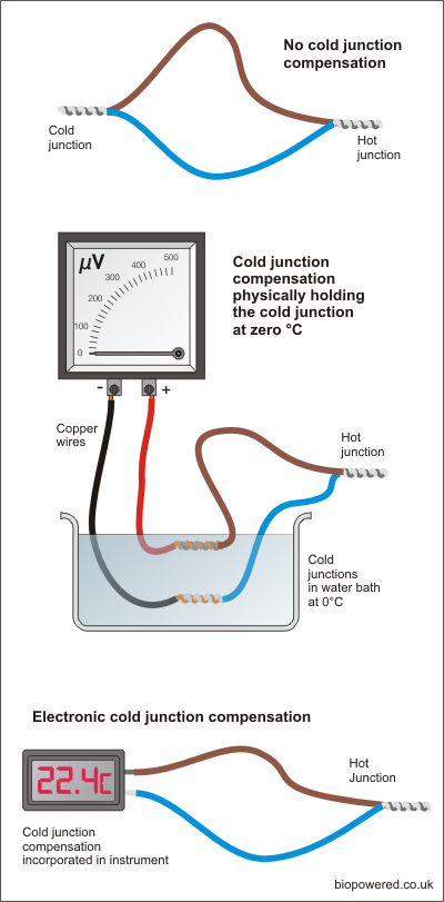
In the early part of the ninetieth century Thomas Seebeck, an Estonian-born German physicist, discovered that in a circuit made with two dissimilar conductor materials, a voltage would be generated whenever there was a difference in temperature between the two junctions.
In the top diagram, right, a voltage will be generated if the right-hand junction is heated. The voltage will be proportional to the temperature, so the hotter the junction the higher the voltage. It’s not quite a linear relationship, but very close. If the voltage were measured and converted to a temperature, the figure arrived at won’t be the actual temperature, it will be the difference in temperature between the hot and the cold junction. So if the cold junction is at an ambient of 22°C and the hot junction at 100°C then the voltage reading will correspond to 78°C.
To make Seebeck’s discovery more practical, the cold junction needs to be at a known temperature. Looking at the centre diagram, using 0°C as a reference for the cold junction means that the temperature corresponding to the voltage generated by the hot junction will be an absolute measurement.
Rather than having bowls of ice water slopping around all over the place, modern instruments contain electronics to replicate the cold junction which makes life a whole lot less complicated as shown in the lower diagram. Whilst the built in cold junction compensation makes life easer in some respects, it makes it a little more complicated in others. You will notice that the system using the water bath uses copper wires to connect to the volt meter. This is normally bad practice when connecting thermocouples as again you have a junction of dissimilar metals which will also generate a voltage if their temperature differs.
In the centre diagram the use of copper wires is possible because both cold junctions are at the same temperature in the water bath. Where the cold junction compensation is located in the instrument it is necessary to use the same, or very similar, conductor materials for the wiring between the thermocouple and the instrument.
To this end you will find that two types of thermocouple wire are available, thermocouple wire and thermocouple extension wire or cable.
The former is wire manufactured from the materials designated for that particular type of thermocouple, which, in the case of a K type thermocouple is chromel (comprising 90% nickel and 10% chromium) and alumel (comprising 95% nickel, 2% manganese, 2% aluminium and 1% silicon)
The latter is manufactured from cheaper alloys, typically copper/constantan for a K type thermocouple, and cannot be used to manufacture thermocouples.
Thermocouple types
Almost any two metals can generate a contact potential, but specific combinations have become standard and are designed to suit different applications.
|
Type |
Conductor materials |
Range
°C |
Output µV/°C |
|
E |
chromel/constantan |
0~1000 |
56 |
|
J |
iron/constantan |
0~700 |
52 |
|
K |
chromel/alumel |
0~1100 |
40 |
|
N |
nicrosil/nisil |
0~1100 |
38 |
|
R |
platinum/PtRh13% |
0~1600 |
10 |
|
S |
platinum/PtRh10% |
0~1600 |
10 |
|
T |
copper/constantan |
-185~300 |
38 |
The most widely used combination of conductor materials is nickel-chrome and nickel-aluminium, known as a type K thermocouple and it is this type that’s best suited to biodiesel processors. It has a broad range, more than covering the temperatures we work with, is widely available and the thermocouples and accessories are reasonably priced.
Thermocouple manufacture
Although two wires of dissimilar metals twisted together will work, commercially thermocouple wires are usually fused together by resistance welding.
This can be done quite easily in the home workshop using a car battery. Bare both ends of the pair of wires and twist together. Put one end on one terminal and just flash the other end on the other terminal. Most thermocouple wire is very thin, so you shouldn’t get a massive spark, but bear in mind that lead acid batteries generate hydrogen so ensure adequate ventilation around the battery top prior to welding.
If the wire is quite thick, it may be safer to hold the twisted end in an oxyacetylene flame if one’s available.
Thermocouples have been made by soldering the two wires together, but with this method you are introducing another dissimilar metal along with possible false readings.
If you do have a go at making your own thermocouple, you need to be aware that thermocouple wire and thermocouple extension wire is available. Thermocouple wire is the only one which will make the correct device. Thermocouple extension wire is not made of the correct metals. It’s constructed from cheaper metal and is intended to connect the thermocouple to the instrument without introducing errors.
The manufacturing process described above produces what is known as an exposed junction thermocouple. In reality it’s probably quicker and cheaper to buy ready made thermocouples which are available in a variety of housings to suit various applications.
Thermocouple housings
Exposed junction
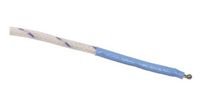
These are the simplest and cheapest types of thermocouples, being the two dissimilar metals fused together as described above, usually with some type of protection like a heat shrink collar for the wires immediately behind the fused bead. Due to the low mass of the fused bead these thermocouples have a very fast response time, but are not suitable for immersion in liquids. For use in liquids or gases, these thermocouples should be used with a pocket or thermowell. Pockets can be purchased but are likely to cost more than the thermocouple. A simple pocket, easily constructed from scrap copper tube, can be made at minimal cost and is shown in the “Tips and wrinkles 1” page here.
Stainless steel sheathed
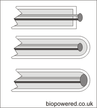
These thermocouples comprise of an exposed junction encapsulated within a metallic tube, or sheath, usually with a closed end. Sheath materials commonly include 304 and 316 stainless steel and Inconel. 304 stainless steel probes are usually the cheapest and are more than adequate for use in all aspects of biodiesel production.
Although usually closed sheathed thermocouples too can have the fused bead exposed as in the top diagram. These offer little advantage over the basic exposed junction unit described above. Two other types of closed probe are available. Ungrounded and grounded.
Ungrounded thermocouples are arranged to have the fused bead electrically isolated from the sheath material. These provide a slow response, but are accurate in that they are unaffected by electrical interference. Grounded thermocouples have a faster response time but can be effected by electrical interference. For the sort of accuracy we need in home biodiesel production, it’s unlikely that electrical interference would cause any problems.
Surface mount
Surface mount thermocouples are unsurprisingly designed to measure temperature of a surface. They usually consist of a probe, the end of which contains a thin metal plate on which the hot junction is mounted. In biodiesel production they are useful for checking the external temperatures of pipes and processors, but will only give an indication of the contents temperature. These probes can also be used to check temperatures of motors if overheating is suspected.
Pipe mount
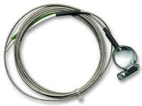
Pipe mount thermocouples come in several forms. the two most common are a clamp type similar to a jump lead clamp and a hose clip type. The latter can be easily made by installing a jubilee clip on the pipe and tucking an exposed junction thermocouple under it. Don't over tighten the jubilee clip. Wrapping it in insulation should give a fairly representative indication of the fluid temperature in the pipe.
Screwed connection
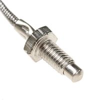
This type of thermocouple is often found individually or, as part of a PID/SSR package, found on on-line auction sites. Although they function perfectly well, they are awkward to mount and are therefore best avoided. Mounting arrangement have been made by making a custom made pocket with the appropriate thread or by removing the nut by squashing the crimp back to circular and sliding the nut off. It can then be slid into a suitable sized pocket.
Thermocouple connectors
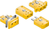
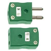
Thermocouple connectors are generally available in two types, mini and standard. As with thermocouple extension wire, their conductors are manufactured from materials that will not introduce additional junction effects.
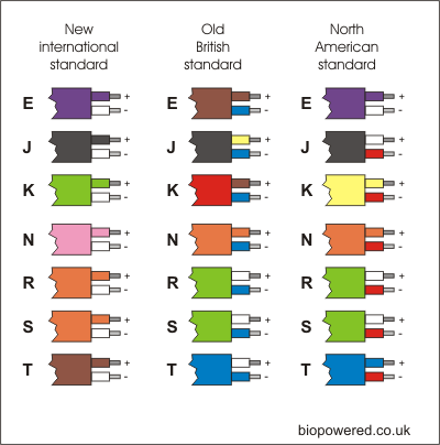
They are colour coded according to thermocouple type. The new IEC international colour codes for connectors match the IEC cable sheath colours, so K type connectors are coloured green. It is still quite common to find connectors sold in the ANSI standard colours and in the case of K types, these are yellow.
Plugs and sockets are available along with panel mount sockets to allow cable entry into a control panel.
For home biodiesel production the mini connectors are probably the most useful as the standard sizes are rather cumbersome and more expensive. When wiring plugs and sockets it's important to maintain the correct polarity on all connections. Most brands of connectors are clearly marked with positive and negative symbols however, for reference, the positive pin is the smaller of the two on both the mini and standard series.
Thermocouple readouts and instruments
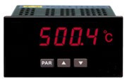
Thermocouples can be connected to PID instruments used to control processor temperatures or to simple readouts, displaying temperature. Readouts are usually digital and vary considerably in price. Those found on online auction sites are adequately accurate for home brew use and can be had for very reasonable prices.
Some readouts are supplied with volt free contacts, these can be used to trigger an alarm or a high temperature shut down of the processor's heater. Typically they will have positive and negative connections for the thermocouple and require a power supply often 12 or 24v DC or 230v AC. Where alarm contacts are fitted, these will have either two or three terminals. Two terminals will be a simple make or break contacts. Three terminal units will comprise common, normally open and normally closed contacts. To alarm on a high, rising temperature use the common and normally open contacts.
Thermocouple switches
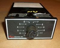
Multi-way switches are available allowing multiple inputs from a number of thermocouples to be switched in sequence to one output. The contacts and terminals of these switches are made from materials which will not introduce an additional junction effect.
These can be useful if you want to use one PID and SSR combination to control from one or more places, or if you have several thermocouples on the processor and only one readout.
For example with a GL processor you may want to control the heater from a thermocouple in the tank whilst processing, but when distilling you may require to control the heater using a still head thermocouple.
