Difference between revisions of "Venturi"
| (8 intermediate revisions by 2 users not shown) | |||
| Line 1: | Line 1: | ||
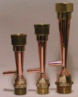
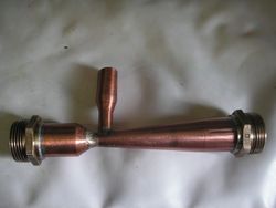
[[File:Jamesrl venturis.jpg|250px|thumb|right|Beautifully crafted copper venturis. Source jamesrl.]] | [[File:Jamesrl venturis.jpg|250px|thumb|right|Beautifully crafted copper venturis. Source jamesrl.]] | ||
| − | A broad definition of a venturi is a device which produces a reduction in pressure due to a constriction of the flow in a pipe. The | + | A broad definition of a venturi is a device which produces a reduction in pressure due to a constriction of the flow in a pipe. The venturi is named after Giovanni Battista Venturi (1746–1822) an Italian physicist, who first discovered the effect. |
Commercially this type of device is known by several names: ejector, injector, eductor, jet pump and air pump and can use various mediums as a motive force, typically air, steam, water, or any other suitable liquid. It can entrain air, liquids, powders and granulated solids. | Commercially this type of device is known by several names: ejector, injector, eductor, jet pump and air pump and can use various mediums as a motive force, typically air, steam, water, or any other suitable liquid. It can entrain air, liquids, powders and granulated solids. | ||
| Line 25: | Line 25: | ||
==History== | ==History== | ||
| − | |||
| − | [http://www.graham-laming.com/bd/main.htm Graham Laming] first introduced the venturi to home | + | [http://www.graham-laming.com/bd/main.htm Graham Laming] first introduced the venturi to home biodiesel production with a relatively simple and easily made devise more along the lines of an [[Simple venturi|oriface plate]]. This important step forward in safety was later developed by jamesrl who, after much research, published a more efficient design which has become widely accepted as a standard by home brewers. |
| − | At a similar time, dickjotec developed | + | At a similar time, dickjotec developed an easily made [[ejector]] design which is used by many as a very effective alternative. |
==Venturi sizing== | ==Venturi sizing== | ||
| + | |||
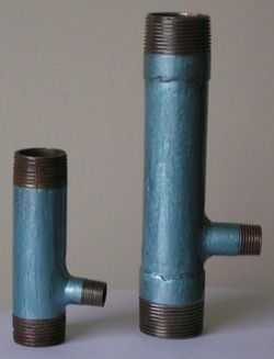
| + | [[File:Jamesrlsteelventuris.jpg|250px|thumb|right|Steel venturis. Source jamesrl.]] | ||
| + | |||
A venturi is designed to operate with a specific flow rate, so before any manufacture can commence the flow rate of the pump being used to drive it must be ascertained. This can be found by looking at the pump performance curve. jamesrl has devised a simple ‘rule of thumb’ formula for venturi throat sizing: | A venturi is designed to operate with a specific flow rate, so before any manufacture can commence the flow rate of the pump being used to drive it must be ascertained. This can be found by looking at the pump performance curve. jamesrl has devised a simple ‘rule of thumb’ formula for venturi throat sizing: | ||
[[File:Jamesrlformula.png]] | [[File:Jamesrlformula.png]] | ||
| − | Where Fr = flow rate at the venturi. | + | Where Fr = flow rate at the venturi in litres per minute, and the result is the throat diameter in millimetres. |
| + | |||
| + | |||
| + | |||
| + | A simple (but practical) approximation of this formula has been offered by therecklessengineer: | ||
| + | |||
| + | [[File:therecklessengineerformula.png]] | ||
| + | |||
| + | Where again Fr = flow rate at the venturi in litres per minute, and the result is the throat diameter in millimetres. | ||
| + | |||
| + | |||
This throat diameter is the only variable which needs calculating when constructing a venturi. All the other dimensions are dictated by pipe size and angles which remain constant, regardless of size. | This throat diameter is the only variable which needs calculating when constructing a venturi. All the other dimensions are dictated by pipe size and angles which remain constant, regardless of size. | ||
[[File:Venturidimensions.png]] | [[File:Venturidimensions.png]] | ||
| − | |||
==Venturi manufacture== | ==Venturi manufacture== | ||
| Line 51: | Line 62: | ||
==Installing a venturi== | ==Installing a venturi== | ||
| − | Although it differs from GL’s original design, common practise currently locates the venturi in the vertical pipe run from the pump and before the bend into the processor, but many constructors locate their venturi in the horizontal pipe immediately before the processor with equal effect, see [[GL processor|here]]. | + | Although it differs from GL’s original processor design, common practise currently locates the venturi in the vertical pipe run from the pump and before the bend into the processor, but many constructors locate their venturi in the horizontal pipe immediately before the processor with equal effect, see [[GL processor|here]]. |
[[File:Fillingventuri.png]] | [[File:Fillingventuri.png]] | ||
| Line 63: | Line 74: | ||
This problem can be prevented in several ways; by having a bend with sufficient resistance to upset the jet but not enough to restrict the flow i.e. a swept or formed bend, by mounting the venturi vertically or a jet breaker. The latter is a simple device involving cross-drilling the pipe immediately down stream of the venturi and soldering a rod across the diameter of the pipe. This rod serves to break the jet, splitting the flow to the outside of the pipe, without causing excessive resistance. At the time of writing the jet breaker pictured is thought to be the only one in use so additional references are needed. It has, however, proved to be very effective and could possibly allow the venturi to discharge directly into the processor. | This problem can be prevented in several ways; by having a bend with sufficient resistance to upset the jet but not enough to restrict the flow i.e. a swept or formed bend, by mounting the venturi vertically or a jet breaker. The latter is a simple device involving cross-drilling the pipe immediately down stream of the venturi and soldering a rod across the diameter of the pipe. This rod serves to break the jet, splitting the flow to the outside of the pipe, without causing excessive resistance. At the time of writing the jet breaker pictured is thought to be the only one in use so additional references are needed. It has, however, proved to be very effective and could possibly allow the venturi to discharge directly into the processor. | ||
| + | <gallery caption="Hand beaten venturi by Graham Laming" widths="300px" heights="200px" perrow="3"> | ||
| + | File:GL hand beaten venturi 1.gif|Hand beaten venturi. Club hammer used as an anvil to obtain approximate angles. Source: Graham Laming. | ||
| + | File:GL hand beaten venturi 2.gif|Part finished, hand beaten venturi. Source: Graham Laming. | ||
| + | File:GL hand beaten venturi 3.gif|Venturi in place on the processor. Source: Graham Laming. | ||
| + | </gallery> | ||
| + | ==See also== | ||
| − | [[ | + | * [[Casting a venturi]] |
[[Category:Biodiesel]] | [[Category:Biodiesel]] | ||
[[Category:Processors and equipment]] | [[Category:Processors and equipment]] | ||
| + | |||
| + | [[User:Bio-rich-time-poor|Bio-rich-time-poor]] 23:43, 3 April 2011 (BST) | ||
Latest revision as of 23:22, 3 March 2013
A broad definition of a venturi is a device which produces a reduction in pressure due to a constriction of the flow in a pipe. The venturi is named after Giovanni Battista Venturi (1746–1822) an Italian physicist, who first discovered the effect. Commercially this type of device is known by several names: ejector, injector, eductor, jet pump and air pump and can use various mediums as a motive force, typically air, steam, water, or any other suitable liquid. It can entrain air, liquids, powders and granulated solids.
Contents
Venturi theory
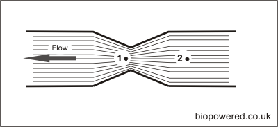
A venturi operates on the Bernoulli's principle, similar to an aircraft wing, where air is forced to pass faster across the upper surface, reducing pressure and creating lift.
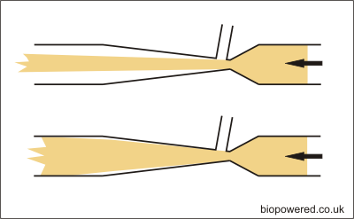
Referring to the diagram above, the same effect is created with flow in a pipe. By forcing the liquid through a constriction, the flow at point 1 is speeded up in comparison to point 2. This results in a reduced pressure at point 1. The theory can be further explored here and here.
Terminology
In the world of home brew Biodiesel the following terminology has generally been accepted as a standard:
- Venturi … device creating suction by means of a constriction.
- Ejector … device creating suction by means of a jet discharging across a gap into a throat and discharge cone.
- Eductor … submerged devise for mixing contents of processor tank.
History
Graham Laming first introduced the venturi to home biodiesel production with a relatively simple and easily made devise more along the lines of an oriface plate. This important step forward in safety was later developed by jamesrl who, after much research, published a more efficient design which has become widely accepted as a standard by home brewers. At a similar time, dickjotec developed an easily made ejector design which is used by many as a very effective alternative.
Venturi sizing
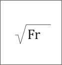
A venturi is designed to operate with a specific flow rate, so before any manufacture can commence the flow rate of the pump being used to drive it must be ascertained. This can be found by looking at the pump performance curve. jamesrl has devised a simple ‘rule of thumb’ formula for venturi throat sizing:
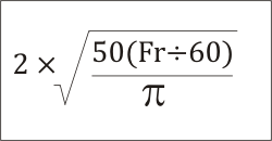
Where Fr = flow rate at the venturi in litres per minute, and the result is the throat diameter in millimetres.
A simple (but practical) approximation of this formula has been offered by therecklessengineer:
Where again Fr = flow rate at the venturi in litres per minute, and the result is the throat diameter in millimetres.
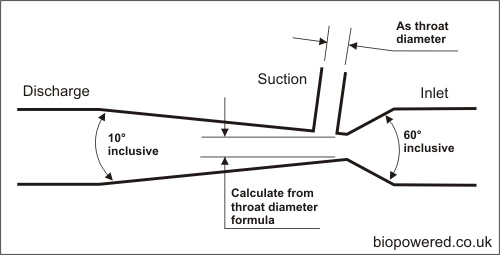
This throat diameter is the only variable which needs calculating when constructing a venturi. All the other dimensions are dictated by pipe size and angles which remain constant, regardless of size.
Venturi manufacture
There are many ways a venturi can be made, many require special equipment, but others are achievable with few tools and just a little skill. See casting a venturi. Other methods include spinning, hand forming and fabrication and turning.
Installing a venturi
Although it differs from GL’s original processor design, common practise currently locates the venturi in the vertical pipe run from the pump and before the bend into the processor, but many constructors locate their venturi in the horizontal pipe immediately before the processor with equal effect, see here.
For a venturi to function correctly the flow from the throat needs to pass along the walls of the discharge cone. In this respect, an ejector is probably superior as its design automatically encourages this effect.
If a venturi is made in such a way that the throat forms a jet, for example with a drilled throat, then the jet will pass straight through the discharge cone without touching the sides and fail to establish suction in the suction port.
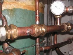
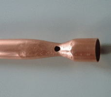
This problem can be prevented in several ways; by having a bend with sufficient resistance to upset the jet but not enough to restrict the flow i.e. a swept or formed bend, by mounting the venturi vertically or a jet breaker. The latter is a simple device involving cross-drilling the pipe immediately down stream of the venturi and soldering a rod across the diameter of the pipe. This rod serves to break the jet, splitting the flow to the outside of the pipe, without causing excessive resistance. At the time of writing the jet breaker pictured is thought to be the only one in use so additional references are needed. It has, however, proved to be very effective and could possibly allow the venturi to discharge directly into the processor.
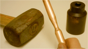
- Hand beaten venturi by Graham Laming
See also
Bio-rich-time-poor 23:43, 3 April 2011 (BST)
