Difference between revisions of "Plumbing fittings"
(→Various) |
|||
| (38 intermediate revisions by 3 users not shown) | |||
| Line 1: | Line 1: | ||
| − | |||
| − | |||
<metadesc>Plumbing fittings & Tools</metadesc> | <metadesc>Plumbing fittings & Tools</metadesc> | ||
| − | + | A brief discription of the fittings and tools used in making a processor or filter set up. | |
| − | A brief discription of the fittings and tools used | ||
| Line 12: | Line 9: | ||
__TOC__ | __TOC__ | ||
| + | ==Pipe== | ||
| + | Available in lengths of upto 6 metres and the 8 and 10 in rolls upto 50 metres. | ||
| + | Diameters include 8,10,15,22 and 28 mm it can be also obtained chrome plated. | ||
| + | <gallery caption="Click pictures to enlarge" widths="300px" heights="300px" perrow="2" align="center"> | ||
| + | File:Copper_pipe.jpg |Copper pipe | ||
| + | File:Chromed_copper_pipe.jpg |Chromed copper pipe | ||
| + | </gallery> | ||
==Fittings== | ==Fittings== | ||
| − | There are basically two types of copper fittings,compression and capillary | + | Fittings are used in pipe and plumbing systems to connect straight pipe or tubing sections, to adapt to different sizes or shapes, and for other purposes. |
| − | A compression fitting comprises of the body an olive and the nut | + | There are basically two types of copper fittings,compression and capillary. |
| − | There are two types of capillary end feed and solder ring/integral ring joint | + | A compression fitting comprises of the body an olive and the nut,the nut is threaded onto the body of the fitting and tightened to make a leakproof connection. Fittings are typically made of brass. |
| + | There are two types of capillary - end feed/copper sweat and yorkshire/solder ring/integral ring joint. | ||
| + | |||
| + | |||
<gallery caption="Click pictures to enlarge" widths="300px" heights="300px" perrow="2" align="center"> | <gallery caption="Click pictures to enlarge" widths="300px" heights="300px" perrow="2" align="center"> | ||
| − | File:Fittings1.jpg |Top row-Straight connector/coupler,Bt row-90/Elbow/Street elbow L-R end feed/ | + | File:Fittings1.jpg |Top row-Straight connector/coupler, Bt row-90/Elbow/Street elbow L-R end feed/yorkshire/compression |
| − | File:Fittings2.jpg |L-R 45 Elbow-End feed,Stopend- | + | File:Fittings2.jpg |L-R 45 Regular Elbow-End feed,Stopend-yorkshire, 22-15 Reducer |
</gallery> | </gallery> | ||
| + | |||
<gallery caption="Click pictures to enlarge" widths="300px" heights="300px" perrow="2" align="center"> | <gallery caption="Click pictures to enlarge" widths="300px" heights="300px" perrow="2" align="center"> | ||
| − | File:Fittings3.jpg |Equal tee- | + | File:End_feed_90.jpg |End feed 90/Elbow |
| + | File:Compression_Straight_coupler.jpg |Straight coupler - Compression | ||
| + | </gallery> | ||
| + | |||
| + | |||
| + | Elbow/90/Street elbow | ||
| + | |||
| + | An elbow is a pipe fitting installed between two lengths of pipe or tubing to allow a change of direction, usually a 90° or 45° angle, though 22.5° elbows are also made. | ||
| + | Most elbows are available in short radius or long radius types. | ||
| + | |||
| + | Coupler/Straight connector | ||
| + | |||
| + | A coupling connects two pipes to each other. If the size of the pipe is not the same, the fitting may be called a reducing coupling or reducer. | ||
| + | |||
| + | Reducer | ||
| + | |||
| + | A reducer allows for a change in pipe size. | ||
| + | <gallery caption="Click pictures to enlarge" widths="300px" heights="300px" perrow="2" align="center"> | ||
| + | File:Fittings3.jpg |Equal tee-Yorkshire,Unequal tee/Reducing tee 22-15-15-End feed | ||
File:Fittings4.jpg |Olive (can be copper or brass),Insert-Nylon/Metal | File:Fittings4.jpg |Olive (can be copper or brass),Insert-Nylon/Metal | ||
</gallery> | </gallery> | ||
| + | |||
| + | <gallery caption="Click pictures to enlarge" widths="300px" heights="300px" perrow="2" align="center"> | ||
| + | File:Olive.jpg |Olive (can be copper or brass) | ||
| + | File:Compression_tee.jpg |Compression tee | ||
| + | </gallery> | ||
| + | |||
| + | |||
| + | Tee | ||
| + | |||
| + | A tee is used to either join or split a flow. Most are tees with the same inlet and outlet sizes, but reducing/unequal tees are available as well. | ||
| + | |||
| + | |||
| + | |||
<gallery caption="Click pictures to enlarge" widths="300px" heights="300px" perrow="2" align="center"> | <gallery caption="Click pictures to enlarge" widths="300px" heights="300px" perrow="2" align="center"> | ||
File:Fittings5.jpg |Tank connector with a nylon and fibre washer | File:Fittings5.jpg |Tank connector with a nylon and fibre washer | ||
| − | File:Fittings6.jpg |L-R 1"BSP to 22mm Metric joiner,22mm | + | File:Fittings6.jpg |L-R 1"BSP to 22mm Metric joiner,22mm Yorkshire to 3/4" BSP Tap connector, Hosetail-Male thread |
</gallery> | </gallery> | ||
| + | |||
| + | Tank connector | ||
| + | |||
| + | Joins pipes to cylinders and cisterns or in our case 45 gal drums. | ||
| + | Do not use the supplied washers with biodiesel as they will deteriorate, replace them with nylon or fibre etc. | ||
| + | |||
<gallery caption="Click pictures to enlarge" widths="300px" heights="300px" perrow="2" align="center"> | <gallery caption="Click pictures to enlarge" widths="300px" heights="300px" perrow="2" align="center"> | ||
File:Fittings7.jpg |Washing machine connectors 3/4" BSP with a 3/4" Tap connector | File:Fittings7.jpg |Washing machine connectors 3/4" BSP with a 3/4" Tap connector | ||
| Line 42: | Line 87: | ||
File:Gate_valve.jpg|Gate valve | File:Gate_valve.jpg|Gate valve | ||
</gallery> | </gallery> | ||
| + | Ball valves/lever valve | ||
| + | A ball valve is a valve with a spherical disc, the part of the valve which controls the flow through it. The sphere has a hole, or port, through the middle so that when the port is in line with both ends of the valve, flow will occur. When the valve is closed, the hole is perpendicular to the ends of the valve, and flow is blocked. The handle or lever will be inline with the port position letting you "see" the valve's position. | ||
| + | Gate valve | ||
| + | |||
| + | A gate valve is a valve that opens by lifting a round or rectangular gate/wedge out of the path of the fluid. | ||
===Other=== | ===Other=== | ||
| + | |||
| + | Fitting a heater flange ring [http://www.biopowered.co.uk/wiki/Fitting_a_heater_flange HowTo] | ||
<gallery caption="Click pictures to enlarge" widths="300px" heights="300px" perrow="2" align="center"> | <gallery caption="Click pictures to enlarge" widths="300px" heights="300px" perrow="2" align="center"> | ||
| − | File:Heater_flange.jpg | | + | File:Heater_flange.jpg |Heater ring (solder on) |
File:Mechanical_flange.jpg|Mechanical flange with fibre washer | File:Mechanical_flange.jpg|Mechanical flange with fibre washer | ||
</gallery> | </gallery> | ||
<gallery caption="Click pictures to enlarge" widths="300px" heights="300px" perrow="2" align="center"> | <gallery caption="Click pictures to enlarge" widths="300px" heights="300px" perrow="2" align="center"> | ||
| − | File:Heater.jpg|Immersion heater,fibre washer and thermostat | + | File:Heater.jpg|Immersion heater, fibre washer and thermostat |
</gallery> | </gallery> | ||
| + | |||
| + | <gallery caption="Click pictures to enlarge" widths="300px" heights="300px" perrow="2" align="center"> | ||
| + | File:Dispensing_nozzle.jpg |Dispensing nozzle | ||
| + | File:Filter.jpg |10" filter housing, element and pressure gauge | ||
| + | </gallery> | ||
| + | |||
| + | Dispensing nozzle | ||
| + | |||
| + | Check that the O rings/seals are biodiesel compatable. | ||
| + | |||
| + | Filter housing | ||
| + | |||
| + | Normally either 3/4" or 1" BSP threads. | ||
| + | |||
| + | If you use PTFE tape when fitting an immersion heater try and get the gas type as it is thicker. | ||
==Tools== | ==Tools== | ||
<gallery caption="Click pictures to enlarge" widths="300px" heights="300px" perrow="2" align="center"> | <gallery caption="Click pictures to enlarge" widths="300px" heights="300px" perrow="2" align="center"> | ||
File:Bender.jpg|Pipe bender with formers | File:Bender.jpg|Pipe bender with formers | ||
| − | File:Box_wrench.jpg| | + | File:Box_wrench.jpg|Immersion heater box spanner and 12v Immersion heater |
</gallery> | </gallery> | ||
<gallery caption="Click pictures to enlarge" widths="300px" heights="300px" perrow="2" align="center"> | <gallery caption="Click pictures to enlarge" widths="300px" heights="300px" perrow="2" align="center"> | ||
File:Pipe_cutters.jpg |Various pipe cutters | File:Pipe_cutters.jpg |Various pipe cutters | ||
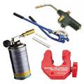
| − | File:Soldering_kit.jpg|Gas torch,solder and flux | + | File:Soldering_kit.jpg|Gas torch, solder and flux |
</gallery> | </gallery> | ||
<gallery caption="Click pictures to enlarge" widths="300px" heights="300px" perrow="2" align="center"> | <gallery caption="Click pictures to enlarge" widths="300px" heights="300px" perrow="2" align="center"> | ||
| − | File:Spanner.jpg | | + | File:Spanner.jpg |Immersion heater spanner |
</gallery> | </gallery> | ||
| + | <gallery caption="Click pictures to enlarge" widths="300px" heights="300px" perrow="2" align="center"> | ||
| + | File:Pipe_bending_spring.jpg |Pipe bending spring | ||
| + | File:Selection_of_tools.jpg |Selection of tools | ||
| + | </gallery> | ||
| + | Using a pipe bender. | ||
| − | + | Hold the pipe against the radiused former, then insert the straight former to support the pipe then pull the levers together. | |
| − | |||
| − | |||
| − | |||
| − | |||
| − | |||
| − | |||
| − | === | + | ===Various=== |
| − | + | Hole size required. | |
| − | + | Mechanical flange 65mm. | |
| + | 22mm Tank connector 1 1/16". | ||
| − | + | 15mm Tank connector 22mm. | |
| + | You can file or drill out the "stop" on tank connectors which will allow the pipe to pass through. | ||
| + | Most pumps i.e. TAM105s have a 1" BSP parellel thread so normally you would need 2 of 22mm compression x 1" BSP for your processor. | ||
| + | 2 1/4" mild steel weldable sockets are available from a vegetableoildiesel forum member and a stainless steel version is obtainable commercially. | ||
| + | For a water washing spray nozzle the brass fitting on a cheap pump up sprayer is ideal. | ||
| − | + | ==Pockets== | |
| + | You can make a pocket for a thermometer or thermocouple by filing out the stop on a 15mm tank connector, pass a short piece of 15mm pipe through this and solder on a 15-10mm or 15-8mm reducer then solder in the required length of 8 or 10mm pipe and solder on an end cap. | ||
| − | == | + | ===Fitting a tank connector in a tight head drum=== |
| − | + | What you need is the tank connector a drill the same size as the threads on the connector 2 nylon washers for each tank connector a length of string and a wire coat hanger. | |
| − | + | How to do it, straighten the coat hanger then grip it with pliers 1/2" from the end and bend it around the plies to make a hook, measure the threads on the tank connector and drill the hole, the threads want to be a tight fit to the hole, tie the nut to the string and drop the nut through the filler hole, keep hold of the string so that you are just holding it off the bottom of the tank put the hook through the hole you have just drilled and hook the string and pull it through the hole, tie it of somewhere so that it wont get pulled back into the tank. | |
| − | + | Next the other end of the string, put 1 nylon washer on to the tank connector up to the flange - you can put silicon sealer on the washer if you want, push the string through the tank connector so that when you pull it into the tank the threaded end enters first. From the flange end make a loop in the string then tie the nut from the tank connector onto the string so that you can pull the tank connector through the hole you drilled, you also want to be able to recover the nut so dont make a quick release knot when you get the threads through the hole pull it up tight so that the flange is against the inside of the tank, then you can recover the string with the 2 nuts on it, then fit another nylon washer and silicon then the check nut and pull up tight put the olive and nut on and you are done. | |
| − | |||
| + | Courtesy of JIM.M | ||
| − | == | + | ==See also== |
| − | |||
| − | |||
| − | |||
| + | * [[Fitting a heater flange ]] | ||
| − | |||
| − | |||
| − | |||
| − | |||
| − | |||
| − | |||
| − | |||
| − | |||
| − | |||
| − | |||
| + | [[User:KH|KH]] 21:30, 17 October 2012 (BST) | ||
| − | |||
| − | |||
| − | |||
| − | + | [[Category:Biodiesel]] | |
| − | |||
| − | |||
| − | |||
| − | |||
| − | |||
| − | |||
| − | |||
| − | |||
[[Category:Processors and equipment]] | [[Category:Processors and equipment]] | ||
| − | |||
| − | |||
| + | [[Category:vegetable oil]] | ||
| − | |||
| − | |||
| − | |||
| − | |||
| − | |||
| − | |||
[[Category:Filtration & drying equipment]] | [[Category:Filtration & drying equipment]] | ||
| − | |||
| − | |||
| − | |||
| − | |||
| − | |||
| − | |||
| − | |||
| − | |||
Latest revision as of 20:34, 1 March 2013
A brief discription of the fittings and tools used in making a processor or filter set up.
Contents
Pipe
Available in lengths of upto 6 metres and the 8 and 10 in rolls upto 50 metres. Diameters include 8,10,15,22 and 28 mm it can be also obtained chrome plated.
- Click pictures to enlarge
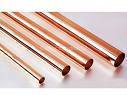
Copper pipe
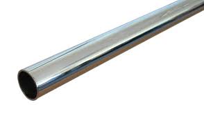
Chromed copper pipe


Fittings
Fittings are used in pipe and plumbing systems to connect straight pipe or tubing sections, to adapt to different sizes or shapes, and for other purposes. There are basically two types of copper fittings,compression and capillary. A compression fitting comprises of the body an olive and the nut,the nut is threaded onto the body of the fitting and tightened to make a leakproof connection. Fittings are typically made of brass. There are two types of capillary - end feed/copper sweat and yorkshire/solder ring/integral ring joint.
- Click pictures to enlarge
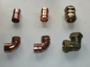
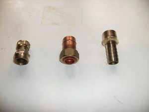
Top row-Straight connector/coupler, Bt row-90/Elbow/Street elbow L-R end feed/yorkshire/compression
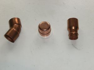
L-R 45 Regular Elbow-End feed,Stopend-yorkshire, 22-15 Reducer


- Click pictures to enlarge
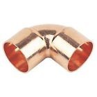
End feed 90/Elbow
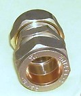
Straight coupler - Compression


Elbow/90/Street elbow
An elbow is a pipe fitting installed between two lengths of pipe or tubing to allow a change of direction, usually a 90° or 45° angle, though 22.5° elbows are also made. Most elbows are available in short radius or long radius types.
Coupler/Straight connector
A coupling connects two pipes to each other. If the size of the pipe is not the same, the fitting may be called a reducing coupling or reducer.
Reducer
A reducer allows for a change in pipe size.
- Click pictures to enlarge
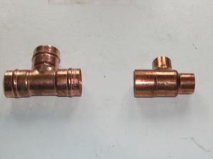
Equal tee-Yorkshire,Unequal tee/Reducing tee 22-15-15-End feed
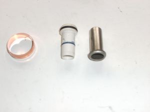
Olive (can be copper or brass),Insert-Nylon/Metal


- Click pictures to enlarge
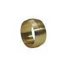
Olive (can be copper or brass)

Compression tee


Tee
A tee is used to either join or split a flow. Most are tees with the same inlet and outlet sizes, but reducing/unequal tees are available as well.
- Click pictures to enlarge
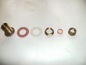
Tank connector with a nylon and fibre washer
L-R 1"BSP to 22mm Metric joiner,22mm Yorkshire to 3/4" BSP Tap connector, Hosetail-Male thread


Tank connector
Joins pipes to cylinders and cisterns or in our case 45 gal drums. Do not use the supplied washers with biodiesel as they will deteriorate, replace them with nylon or fibre etc.
- Click pictures to enlarge
Washing machine connectors 3/4" BSP with a 3/4" Tap connector

Valves
- Click pictures to enlarge
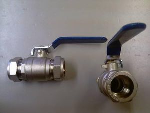
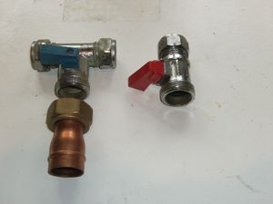
Ball lever valve (always use full bore)
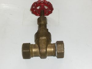
Gate valve


Ball valves/lever valve
A ball valve is a valve with a spherical disc, the part of the valve which controls the flow through it. The sphere has a hole, or port, through the middle so that when the port is in line with both ends of the valve, flow will occur. When the valve is closed, the hole is perpendicular to the ends of the valve, and flow is blocked. The handle or lever will be inline with the port position letting you "see" the valve's position.
Gate valve
A gate valve is a valve that opens by lifting a round or rectangular gate/wedge out of the path of the fluid.
Other
Fitting a heater flange ring HowTo
- Click pictures to enlarge
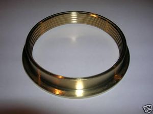
Heater ring (solder on)
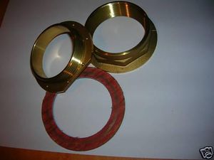
Mechanical flange with fibre washer


- Click pictures to enlarge
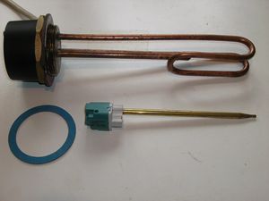
Immersion heater, fibre washer and thermostat

- Click pictures to enlarge
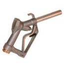
Dispensing nozzle
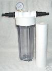
10" filter housing, element and pressure gauge


Dispensing nozzle
Check that the O rings/seals are biodiesel compatable.
Filter housing
Normally either 3/4" or 1" BSP threads.
If you use PTFE tape when fitting an immersion heater try and get the gas type as it is thicker.
Tools
- Click pictures to enlarge
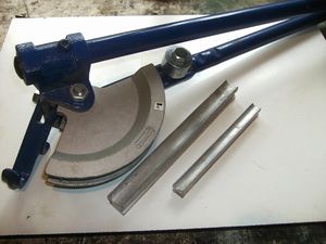
Pipe bender with formers
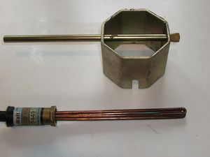
Immersion heater box spanner and 12v Immersion heater


- Click pictures to enlarge
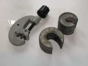
Various pipe cutters
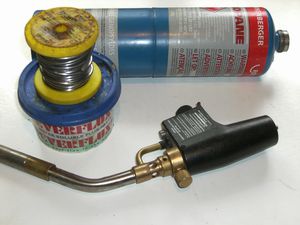
Gas torch, solder and flux


- Click pictures to enlarge
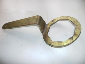
Immersion heater spanner

- Click pictures to enlarge
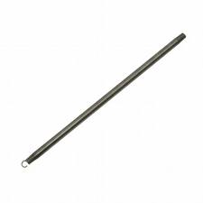
Pipe bending spring
Selection of tools


Using a pipe bender.
Hold the pipe against the radiused former, then insert the straight former to support the pipe then pull the levers together.
Various
Hole size required.
Mechanical flange 65mm.
22mm Tank connector 1 1/16".
15mm Tank connector 22mm.
You can file or drill out the "stop" on tank connectors which will allow the pipe to pass through.
Most pumps i.e. TAM105s have a 1" BSP parellel thread so normally you would need 2 of 22mm compression x 1" BSP for your processor.
2 1/4" mild steel weldable sockets are available from a vegetableoildiesel forum member and a stainless steel version is obtainable commercially.
For a water washing spray nozzle the brass fitting on a cheap pump up sprayer is ideal.
Pockets
You can make a pocket for a thermometer or thermocouple by filing out the stop on a 15mm tank connector, pass a short piece of 15mm pipe through this and solder on a 15-10mm or 15-8mm reducer then solder in the required length of 8 or 10mm pipe and solder on an end cap.
Fitting a tank connector in a tight head drum
What you need is the tank connector a drill the same size as the threads on the connector 2 nylon washers for each tank connector a length of string and a wire coat hanger.
How to do it, straighten the coat hanger then grip it with pliers 1/2" from the end and bend it around the plies to make a hook, measure the threads on the tank connector and drill the hole, the threads want to be a tight fit to the hole, tie the nut to the string and drop the nut through the filler hole, keep hold of the string so that you are just holding it off the bottom of the tank put the hook through the hole you have just drilled and hook the string and pull it through the hole, tie it of somewhere so that it wont get pulled back into the tank. Next the other end of the string, put 1 nylon washer on to the tank connector up to the flange - you can put silicon sealer on the washer if you want, push the string through the tank connector so that when you pull it into the tank the threaded end enters first. From the flange end make a loop in the string then tie the nut from the tank connector onto the string so that you can pull the tank connector through the hole you drilled, you also want to be able to recover the nut so dont make a quick release knot when you get the threads through the hole pull it up tight so that the flange is against the inside of the tank, then you can recover the string with the 2 nuts on it, then fit another nylon washer and silicon then the check nut and pull up tight put the olive and nut on and you are done.
Courtesy of JIM.M
See also
KH 21:30, 17 October 2012 (BST)