Difference between revisions of "Melting stick"
| Line 16: | Line 16: | ||
The unit described here is based on a 300W unit, a size which has proved satisfactory for melting volumes of 20 litres and greater. The design of the "tosser tube" is sufficiently compact to fit through screw top lids of plastic cubies and 20 litre tins. | The unit described here is based on a 300W unit, a size which has proved satisfactory for melting volumes of 20 litres and greater. The design of the "tosser tube" is sufficiently compact to fit through screw top lids of plastic cubies and 20 litre tins. | ||
| + | <br> | ||
| + | <br> | ||
| + | <br> | ||
| + | <br> | ||
| + | |||
| + | <blockquote style="background-color: lightgrey; border: solid thin grey;"> | ||
| + | Although known by some low lifes as a tosser tube it is really a modern red hot poker and can be demonstrated on said low life! | ||
| + | </blockquote> | ||
| + | ::Quote source: K.H | ||
| + | |||
| + | <br> | ||
| + | <br> | ||
| + | <br> | ||
<br> | <br> | ||
| Line 21: | Line 34: | ||
[[File:Melting stick components.jpg|350px|thumb|left|Components used. Source K.H]] | [[File:Melting stick components.jpg|350px|thumb|left|Components used. Source K.H]] | ||
| + | [[File:Melting stick components.jpg|350px|thumb|center|Awaiting new photo from ???. Source ???]] | ||
| + | <br> | ||
| + | <br> | ||
# ... 1 off ... cartridge heater 15mm outside diamater, 300W (available in various wattages) | # ... 1 off ... cartridge heater 15mm outside diamater, 300W (available in various wattages) | ||
| Line 41: | Line 57: | ||
| − | Solder the stand-off to a compression nut. This is to keep the heater away from the container walls and the curl at the end prevents contact with the container bottom. | + | Solder the stand-off to a compression nut. This is to keep the heater away from the container walls and the curl at the end prevents contact with the container bottom. |
| − | |||
| − | |||
| − | |||
| − | + | Connect the heater cable tails to the power cable by soldering and insulating with the heat-shrink, ensuring that the sleeve is securely attached and cannot slide away from the joint. Alternatively crimp connectors can be employed and, for additional safety, can be covered with heat-shrink sleeveing. Cutting one heater cable tail slightly shorter than the other, will ensure the joints are staggered making it easer to insert the cabling into the tube. | |
| + | Tighten the heater into a straight 15 mm compression fitting using the nut with the stand off attached, then attach the copper 15 mm copper pipe to the other end of the fitting, feeding the cable through the pipe as it's assembled. The copper pipe needs to be long enough to prevent the plastic pipe from becoming too hot. | ||
| + | Attach the second 15 mm compression fitting to the other end of the copper pipe, by carefully threading onto the cable. Feed the cable through the pipe insert and the plastic pipe, and tighten the second compression fitting. | ||
| − | + | Disassemble the cable gland and slide over the cable. The pipe ID is the correct tapping size for the gland thread. If a chamfer is put on the inside of the pipe, it should be possible to screw the gland into position, the metal forming a thread as it's screwed in (warming the pipe may assit in this procedure). Take care not to wind up the cable as you install the gland body, or fit the gland before threading onto the cable. | |
| − | |||
| − | |||
| − | |||
| − | |||
| − | |||
| − | |||
| − | |||
| − | |||
| − | |||
| − | |||
| − | |||
| − | |||
| − | |||
| − | |||
| + | Assemble the rest of the gland, ensuring that the cable is slack within the pipe and gripped satisfactorily so it anchors the cable if pulled. | ||
| + | An inline switch fitted to the cable makes for easier operation. | ||
| + | <br> | ||
| + | <br> | ||
| + | <gallery widths="250px" heights="200px" perrow="3" align="center"> | ||
| + | File:Melting_stick_0013.jpg|15mm dia, 300W cartridge heater. Source: K.H | ||
| + | File:Melting_stick_001.jpg|Completed melting stick. Source: K.H | ||
| + | File:Melting_stick_006.jpg|Melting stick in action. Source: K.H | ||
| + | </gallery> | ||
| + | {{#ev:youtube|5dSujLHjIKs|400|center|Melting stick in action. Source: K.H}} | ||
| + | <br> | ||
| + | <br> | ||
| + | <br> | ||
| + | <br> | ||
| + | <br> | ||
| + | <br> | ||
| + | ==See also== | ||
| − | |||
| − | |||
| − | |||
| − | |||
| − | |||
| Line 91: | Line 104: | ||
| − | [[Category: | + | [[Category:Biodiesel]] |
| + | [[Category:Processors and equipment]] | ||
| + | [[Category:Vegetable oil]] | ||
[[Category:Filtration & drying equipment]] | [[Category:Filtration & drying equipment]] | ||
| − | |||
| − | |||
| − | |||
| − | |||
| − | |||
Revision as of 21:28, 27 October 2012

This is a useful, easily made item used to melt solid oil, palm oil, Glycerine and whites.
Contents
Overview
The melting stick is constructed using a 220-240 volt cartridge heater. These are readily available from on-line auction sites and other outlets. The heaters are available in 110v and 230v versions and are offered in a range of Wattages from 150W to 600W.
The unit described here is based on a 300W unit, a size which has proved satisfactory for melting volumes of 20 litres and greater. The design of the "tosser tube" is sufficiently compact to fit through screw top lids of plastic cubies and 20 litre tins.
Although known by some low lifes as a tosser tube it is really a modern red hot poker and can be demonstrated on said low life!
- Quote source: K.H
Components

- ... 1 off ... cartridge heater 15mm outside diamater, 300W (available in various wattages)
- ... 1 off ... short length of 15mm copper pipe
- ... 2ft ... 15mm plastic pipe
- ... 2 off ... 15mm - 15mm straight compression fitting
- ... 1 off ... plastic pipe insert
- ... 1 off ... Stand-off (piece of metal slightly longer than the heater with the end bent over)
- ... 1 off ... cable and plug
- ... 1 off ... in line power switch
- ... 2 off ... insulated crimp connectors
- ... 2 off ... shrink sleeving
- ... 1 off ... Gp7 brass cable gland
Assembly
Solder the stand-off to a compression nut. This is to keep the heater away from the container walls and the curl at the end prevents contact with the container bottom.
Connect the heater cable tails to the power cable by soldering and insulating with the heat-shrink, ensuring that the sleeve is securely attached and cannot slide away from the joint. Alternatively crimp connectors can be employed and, for additional safety, can be covered with heat-shrink sleeveing. Cutting one heater cable tail slightly shorter than the other, will ensure the joints are staggered making it easer to insert the cabling into the tube.
Tighten the heater into a straight 15 mm compression fitting using the nut with the stand off attached, then attach the copper 15 mm copper pipe to the other end of the fitting, feeding the cable through the pipe as it's assembled. The copper pipe needs to be long enough to prevent the plastic pipe from becoming too hot.
Attach the second 15 mm compression fitting to the other end of the copper pipe, by carefully threading onto the cable. Feed the cable through the pipe insert and the plastic pipe, and tighten the second compression fitting.
Disassemble the cable gland and slide over the cable. The pipe ID is the correct tapping size for the gland thread. If a chamfer is put on the inside of the pipe, it should be possible to screw the gland into position, the metal forming a thread as it's screwed in (warming the pipe may assit in this procedure). Take care not to wind up the cable as you install the gland body, or fit the gland before threading onto the cable.
Assemble the rest of the gland, ensuring that the cable is slack within the pipe and gripped satisfactorily so it anchors the cable if pulled.
An inline switch fitted to the cable makes for easier operation.
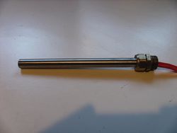
15mm dia, 300W cartridge heater. Source: K.H
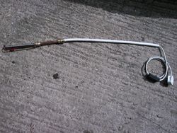
Completed melting stick. Source: K.H
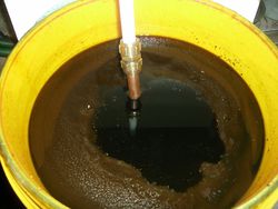
Melting stick in action. Source: K.H


