Unused files
The following files exist but are not embedded in any page. Please note that other web sites may link to a file with a direct URL, and so may still be listed here despite being in active use.
Showing below up to 100 results in range #1 to #100.
View (previous 100 | next 100) (20 | 50 | 100 | 250 | 500)
 Venturi geometry.gif 500 × 207; 3 KB
 Venturi dimensions.gif 600 × 182; 6 KB
 Biopowered logo.png 230 × 69; 4 KB
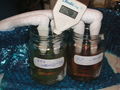
 Soapy bio.jpg 240 × 320; 10 KB
 TAM105 impeller.jpg 640 × 480; 87 KB
 10ml burette.jpg 480 × 640; 85 KB
 10ml field burette.jpg 480 × 640; 86 KB
 25ml lab burette.jpg 480 × 640; 92 KB
 Settle drum clean out.jpg 640 × 480; 80 KB
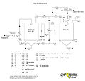 Schematic diagram.jpg 600 × 574; 109 KB
 TT700A 01.jpg 600 × 717; 112 KB
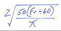 Venturi Formula.jpg 350 × 177; 9 KB
 Wiki logo1.jpg 1,512 × 831; 67 KB
 Wiki logo.png 1,512 × 831; 198 KB
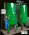
 Full view 1.jpg 1,765 × 1,250; 250 KB
 Untitled-3.jpg 320 × 240; 17 KB
 Kh.JPG 1,218 × 640; 88 KB
 Kh1.JPG 826 × 640; 51 KB
 Carboy vented lid.gif 279 × 320; 52 KB
 Wiki creating pages.png 500 × 700; 104 KB
 Wiki login.png 500 × 700; 47 KB
 Tam1051-1.jpg 640 × 613; 55 KB
 Tam1051.jpg 640 × 419; 36 KB
 Pug filter.jpg 359 × 520; 30 KB
 Temp-sender-twin.jpg 810 × 444; 34 KB
 Temp-sender-twin2.JPG 810 × 444; 28 KB
 GL processor schematic.cdr ; 28 KB
 Temp-twin2.JPG 810 × 444; 27 KB
- Wiki graphics master.cdr ; 26 KB
 Paint test.PNG 654 × 400; 11 KB
 Dryer with sparge pipe.png 400 × 515; 31 KB
 Silver soldered venturi body.png 600 × 310; 483 KB
 Wiki graphics master.png 600 × 693; 76 KB
 Peugeot 406 fuel strainer removal 1.jpg 640 × 480; 82 KB
 Peugeot 406 fuel strainer removal 2.jpg 640 × 480; 94 KB
 Peugeot 406 fuel strainer removal 3.jpg 640 × 480; 103 KB
 Peugeot 406 fuel strainer removal 4.jpg 640 × 480; 87 KB
 Peugeot 406 fuel strainer removal 5.jpg 640 × 480; 95 KB
 Peugeot 406 fuel strainer removal 6.jpg 640 × 480; 117 KB
 Bypass valve and added ball valve.jpg 3,648 × 2,736; 765 KB
 Set up 005.jpg 3,648 × 2,736; 755 KB
 WVO system 6-5-11 006.jpg 3,648 × 2,736; 731 KB
 Set up 009.jpg 3,648 × 2,736; 654 KB
 Set up 011.jpg 3,648 × 2,736; 886 KB
 Set up 015.jpg 2,736 × 3,648; 948 KB
 Set up 016.jpg 2,736 × 3,648; 747 KB
 Float switch.jpg 3,648 × 2,736; 728 KB
 Sight tube added.jpg 2,736 × 3,648; 737 KB
 Simple fat melting tank.JPG 1,536 × 2,048; 593 KB
 Chain drill.JPG 2,048 × 1,536; 750 KB
 File out.JPG 2,048 × 1,536; 759 KB
 Weld tube.JPG 2,048 × 1,536; 719 KB
 Modified KH processor.jpg 640 × 480; 79 KB
 4 port venturi5.JPG 2,048 × 1,536; 662 KB
 Conversion pipe.jpg 3,648 × 2,736; 735 KB
 Float switch 001.jpg 2,736 × 3,648; 892 KB
 Meth att 002.jpg 1,600 × 1,200; 494 KB
 Kh-new-pic.JPG 782 × 817; 50 KB
 3in1 002.jpg 3,648 × 2,736; 1 MB
 3in1 003.jpg 2,736 × 3,648; 822 KB
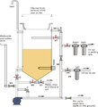 KH multi tasking processor draft 3.png 600 × 663; 62 KB
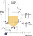 KH multi tasking processor draft 4.png 600 × 663; 61 KB
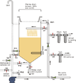 KH multi tasking processor draft 5.png 600 × 663; 74 KB
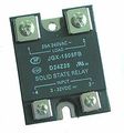 SSR.jpg 217 × 232; 8 KB
 FPHE glued.jpg 3,648 × 2,736; 668 KB
 Pressurised pourer 2.jpg 160 × 120; 6 KB
 Pressurised pourer 1.jpg 160 × 120; 6 KB
 Pressurised pourer 3.jpg 160 × 120; 6 KB
 BCB.JPG 2,048 × 1,536; 708 KB
 Jcloth1 sourceBB.jpg 1,024 × 766; 124 KB
 PDclose.JPG 2,048 × 1,536; 689 KB
 Wiring6.jpg 639 × 452; 42 KB
- GLStatediagraminMSword.doc ; 64 KB
 GLstatediagram.JPG 1,101 × 710; 138 KB
 Gl process 01.png 960 × 720; 78 KB
 N2006P PID step by step.pdf ; 311 KB
- N2006P PID Installation & Wiring.pdf ; 474 KB
- TET-612 PID Manual.pdf ; 313 KB
- TET-612 PID Manual.doc ; 637 KB
- TET-612 PID via Corel.pdf ; 287 KB
- Styilong YL-6E English Manual.pdf ; 236 KB
 Styilong YL-6E English Specifications.gif 702 × 2,065; 126 KB
- WH7016C instructions.pdf ; 121 KB
 JP KH comparison 1.JPG 2,048 × 1,536; 721 KB
 JP KH comparison 2.JPG 2,048 × 1,536; 714 KB
- Oil limit 2500 check7.xls ; 56 KB
- 2500 limit check.xls ; 17 KB
 JP KH comparison at 24hrs.JPG 2,048 × 1,536; 706 KB
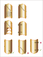 UK Cu cylinders.png 800 × 1,061; 120 KB
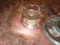 Flange silver soldered to fitting.JPG 2,048 × 1,536; 740 KB
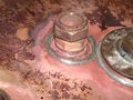 Silver soldered flange soft soldered to tank.JPG 2,048 × 1,536; 753 KB
 Tank connector soldered in position.JPG 2,048 × 1,536; 716 KB
 Week of chilling 1.JPG 2,560 × 1,920; 954 KB
 Week of chilling 2.JPG 2,560 × 1,920; 1.09 MB
 Week of chilling 3.JPG 2,048 × 1,536; 704 KB
 Week of chilling JP.JPG 2,560 × 1,920; 1.18 MB
 Week of chilling KH.JPG 2,560 × 1,920; 1.19 MB


