Uncategorised files
Showing below up to 314 results in range #501 to #814.
View (previous 500 | next 500) (20 | 50 | 100 | 250 | 500)
 PPO impeller after 1.jpg 640 × 480; 187 KB
 PPO impeller after 2.jpg 640 × 480; 144 KB
 PPO impeller after 3.jpg 640 × 480; 145 KB
 PPO impeller after 4.jpg 640 × 480; 215 KB
 PPO impeller before.jpg 640 × 480; 166 KB
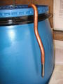
 Packing tape closing one end of a Glog tube.JPG 2,560 × 1,920; 941 KB
 Paint test.PNG 654 × 400; 11 KB
 Parts.jpg 160 × 120; 7 KB
 Peugeot 406 fuel strainer removal 1.jpg 640 × 480; 82 KB
 Peugeot 406 fuel strainer removal 2.jpg 640 × 480; 94 KB
 Peugeot 406 fuel strainer removal 3.jpg 640 × 480; 103 KB
 Peugeot 406 fuel strainer removal 4.jpg 640 × 480; 87 KB
 Peugeot 406 fuel strainer removal 5.jpg 640 × 480; 95 KB
 Peugeot 406 fuel strainer removal 6.jpg 640 × 480; 117 KB
 Peugeot 406 fuel strainer removal 7.jpg 640 × 480; 85 KB
 Pick up pipe 1.JPG 2,048 × 1,536; 682 KB
 Pick up pipe 2.JPG 1,536 × 2,048; 696 KB
 Pipe bending spring.jpg 225 × 225; 2 KB
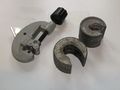 Pipe cutters.jpg 3,648 × 2,736; 448 KB
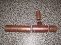 Pipe fitting venturi body.jpg 600 × 450; 105 KB
 Pipe fittings.jpg 600 × 450; 102 KB
 Pipe thermocouple.jpg 268 × 200; 13 KB
 Pipe with flux.jpg 600 × 450; 48 KB
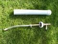
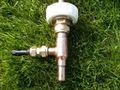
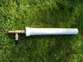
 Plant sprayer nozzle.JPG 1,536 × 2,048; 664 KB
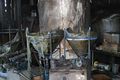 PlasticVesselFire.jpg 700 × 467; 68 KB
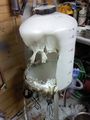 PlasticVesselMelt1.jpg 293 × 390; 20 KB
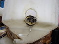 PlasticVesselMelt2.jpg 320 × 240; 11 KB
 Plastic can cap 1.03.stl ; 2.41 MB
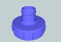 Plastic can cap i1-1.jpg 1,276 × 882; 102 KB
 Plastic can cap i1-2.jpg 1,276 × 882; 168 KB
 Pocket 1.JPG 2,048 × 1,536; 723 KB
 Pocket 2.jpg 300 × 277; 8 KB
 Polishtankgearpumpview zpsefda5734.jpg 2,448 × 3,264; 879 KB
 Prefilter 2.jpg 3,648 × 2,736; 843 KB
 Prep tub lid.JPG 800 × 600; 91 KB
 Prep tub lid being cut.jpg 800 × 600; 106 KB
 Preparation for silver soldering.JPG 2,048 × 1,536; 745 KB
 Pressurised pourer 1.jpg 160 × 120; 6 KB
 Pressurised pourer 2.jpg 160 × 120; 6 KB
 Pressurised pourer 3.jpg 160 × 120; 6 KB
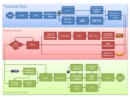 Process flowchart 01.png 960 × 720; 50 KB
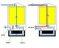
 Processor with combined preheat and wash tank.png 1,012 × 786; 115 KB
 Pug filter.jpg 359 × 520; 30 KB
 Pump pipwork.jpg 3,648 × 2,736; 1.11 MB
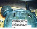
 RM filter mod 1.jpg 490 × 368; 41 KB
 RM filter mod 10.jpg 490 × 368; 40 KB
 RM filter mod 2.jpg 490 × 368; 38 KB
 RM filter mod 3.jpg 490 × 368; 36 KB
 RM filter mod 4.jpg 490 × 368; 23 KB
 RM filter mod 5.jpg 490 × 368; 33 KB
 RM filter mod 6.jpg 490 × 368; 42 KB
 RM filter mod 7.jpg 490 × 368; 37 KB
 RM filter mod 8.jpg 490 × 368; 35 KB
 RM filter mod 9.jpg 490 × 388; 41 KB
 RM filter mod diagram.jpg 708 × 579; 38 KB
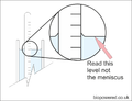 Read hydrometer.png 800 × 611; 57 KB
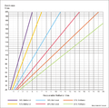 Recoverable Methanol chart.png 800 × 794; 114 KB
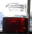
 Red reside from biodiesel mixed with mineral fuel.jpg 320 × 240; 20 KB
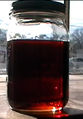
 Red reside from biodiesel mixed with mineral fuel 2.jpg 640 × 480; 57 KB
 Resin tower parts.jpg 3,648 × 2,736; 567 KB
 Ring-1.jpg 640 × 480; 80 KB
 Ring-10.jpg 640 × 480; 78 KB
 Ring-11.jpg 640 × 480; 76 KB
 Ring-12.jpg 640 × 480; 90 KB
 Ring-2.jpg 640 × 480; 87 KB
 Ring-3.jpg 640 × 480; 79 KB
 Ring-4.jpg 640 × 480; 79 KB
 Ring-5.jpg 640 × 480; 92 KB
 Ring-6.jpg 640 × 480; 113 KB
 Ring-7.jpg 640 × 480; 83 KB
 Ring-8.jpg 640 × 480; 98 KB
 Ring-9.jpg 640 × 480; 79 KB
 Rm-filtration.jpg 816 × 612; 94 KB
 Rolling heater tube.JPG 2,048 × 1,536; 723 KB
 Rotary IP.gif 2,000 × 1,300; 63 KB
 SHHE1 julian.JPG 2,048 × 1,536; 753 KB
 SHHE2 julian.JPG 2,048 × 1,536; 727 KB
 SHHE3 julian.JPG 2,048 × 1,536; 697 KB
 SHHE photo1 source Mark.jpg 640 × 480; 90 KB
 SHHE photo2 source Mark.jpg 480 × 640; 100 KB
 SHHE photo3 source Mark.jpg 640 × 480; 42 KB
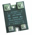 SSR.jpg 217 × 232; 8 KB
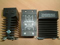 SSR and Heatsink.jpg 500 × 375; 27 KB
 SSR melted.JPG 800 × 1,067; 222 KB
 Samples.JPG 800 × 600; 115 KB
 Schematic diagram.jpg 600 × 574; 109 KB
 Scoopingouttheglyc.jpg 640 × 480; 141 KB
 Screwed TC.jpg 600 × 600; 34 KB
 Seed tray for cans.JPG 800 × 600; 111 KB
 Selection of glyc logs.jpg 1,024 × 768; 219 KB
 Selection of tools.jpg 120 × 120; 3 KB
 Set up 005.jpg 3,648 × 2,736; 755 KB
 Set up 009.jpg 3,648 × 2,736; 654 KB
 Set up 011.jpg 3,648 × 2,736; 886 KB
 Set up 015.jpg 2,736 × 3,648; 948 KB
 Set up 016.jpg 2,736 × 3,648; 747 KB
 Settle drum clean out.jpg 640 × 480; 80 KB
 Side view.jpg 2,736 × 3,648; 1,005 KB
 Sight tube added.jpg 2,736 × 3,648; 737 KB
 Silver solder applied.JPG 2,048 × 1,536; 730 KB
 Silver solder runs around joint.JPG 2,048 × 1,536; 718 KB
 Silver soldered flange soft soldered to tank.JPG 2,048 × 1,536; 753 KB
 Silver soldered pipe connections on a FPHE.png 600 × 507; 675 KB
 Silver soldered venturi body.png 600 × 310; 483 KB
 Simple fat melting tank.JPG 1,536 × 2,048; 593 KB
 Simple fat melting tank.jpg 1,536 × 2,048; 503 KB
 Soap neutralisation washing sample during first wash.JPG 2,560 × 1,920; 984 KB
 Soap neutralisation washing wash waster first 4 washes.JPG 2,560 × 1,920; 894 KB
 Soap test 1.jpg 640 × 480; 100 KB
 Soap test laser fail.jpg 480 × 640; 28 KB
 Soap test laser pass.jpg 480 × 640; 26 KB
 Soap test newspaper.jpg 223 × 297; 15 KB
 SoapwaterL-R1hr3hr6hr-1.jpg 640 × 480; 132 KB
 Soapy bio.jpg 240 × 320; 10 KB
 Sock filter 1.JPG 2,048 × 1,536; 717 KB
 Sock filter 2.JPG 2,048 × 1,536; 680 KB
 Sock filter diagram.png 400 × 436; 56 KB
 Solder running.jpg 600 × 442; 58 KB
 Soldering equipment.jpg 400 × 533; 63 KB
 Soldering kit.jpg 3,648 × 2,736; 621 KB
 Sooty flame.JPG 1,536 × 2,048; 622 KB
 Spanner.jpg 3,648 × 2,736; 428 KB
 Spoon diffuser 1 - Uberveg.jpg 604 × 401; 39 KB
 Spoon diffuser 2 - Uberveg.jpg 604 × 401; 41 KB
 Spunventuri.jpg 600 × 450; 36 KB
 Stacked cubies - Keef.jpg 576 × 1,024; 48 KB
 Storage bottles.jpg 600 × 533; 59 KB
 Straight switch.jpg 120 × 160; 3 KB
 Strong back 1.jpg 640 × 480; 79 KB
 Strong back 2.jpg 640 × 480; 112 KB
 Styilong YL-6E English Manual.pdf ; 236 KB
 Styilong YL-6E English Specifications.gif 702 × 2,065; 126 KB
 Suspended-oil-jug.jpg 816 × 612; 55 KB
 SwitchVeg.jpg 255 × 191; 7 KB
 Symbol - corrosive.jpg 249 × 253; 18 KB
 Symbol - harmful.jpg 249 × 254; 14 KB
 Symbol - highly flam.jpg 249 × 253; 15 KB
 Symbol - toxic.jpg 249 × 253; 19 KB
 TAM105 impeller.jpg 640 × 480; 87 KB
- TAM105 instructions.pdf ; 486 KB
 TAM120-New design.jpg 800 × 800; 57 KB
 TAM120-Old design.jpg 800 × 600; 101 KB
 TAM120 burnt capacitor.jpg 800 × 600; 141 KB
 TAM120 melted terminal block.jpg 800 × 600; 151 KB
 TAM120 new capacitor.jpg 800 × 600; 82 KB
 TAM 105 terminal box.png 1,276 × 850; 66 KB
 TAM 105 terminal box 1.jpg 800 × 600; 107 KB
 TAM 105 terminal box 2.jpg 800 × 600; 79 KB
 TAM 105 terminal box assy.jpg 1,276 × 850; 89 KB
 TAM 105 terminal box lid.png 1,276 × 850; 39 KB
- TAM 105 terminal box lid.stl ; 842 KB
 TAM 105 terminal box top.jpg 1,276 × 850; 123 KB
 TAM 120 broken cooling fan.jpg 800 × 600; 88 KB
 TAM 120 cooling fan.png 1,276 × 850; 127 KB
 TAM 120 cooling fan i2.jpg 800 × 600; 109 KB
 TAM 120 cooling fan i2.png 1,276 × 850; 113 KB
- TAM 120 cooling fan i2.stl ; 995 KB
 TAM 120 cooling fan print.jpg 800 × 600; 125 KB
- TAM 120 terminal box.stl ; 1.12 MB
- TAM 120 terminal box 3D.pdf ; 106 KB
 TAM 120 terminal box bottom.jpg 1,276 × 850; 102 KB
 TAM 120 terminal box fitted.JPG 800 × 600; 127 KB
 TAM 120 terminal box printed.jpg 800 × 600; 118 KB
 TAM 120 terminal box top.jpg 1,276 × 850; 71 KB
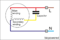 TAM 120 wiring dia.png 500 × 330; 28 KB
 TC probe tip types.png 300 × 335; 13 KB
 TCprincipals.png 400 × 811; 80 KB
- TET-612 PID Manual.doc ; 637 KB
- TET-612 PID Manual.pdf ; 313 KB
- TET-612 PID via Corel.pdf ; 287 KB
 TT700A 01.jpg 600 × 717; 112 KB
 Tam105-pump.jpg 816 × 612; 84 KB
 Tam1051-1.jpg 640 × 613; 55 KB
 Tam1051.jpg 640 × 419; 36 KB
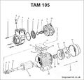 Tam105 exploded diagram.jpg 700 × 670; 80 KB
 Tam 01 Rob-b.jpg 3,264 × 1,840; 513 KB
 Tam 02 Rob-b.jpg 3,264 × 1,840; 519 KB
 Tam 03 Rob-b.jpg 3,264 × 1,840; 610 KB
 Tam 04 Rob-b.jpg 3,264 × 1,840; 526 KB
 Tam 05 Rob-b.jpg 3,264 × 1,840; 676 KB
 Tam 120 cooling fan i2 shaft fit.jpg 5,333 × 4,000; 2.69 MB
 Tank-lag1.jpg 653 × 490; 38 KB
 Tank-lag2.jpg 653 × 490; 53 KB
 Tank base 1.jpg 519 × 395; 42 KB
 Tank base 2.jpg 527 × 395; 43 KB
 Tank connector soldered in position.JPG 2,048 × 1,536; 716 KB
 Technopolymer impeller 1.jpg 480 × 640; 107 KB
 Technopolymer impeller 2.jpg 480 × 640; 84 KB
 Tellerini pump.jpg 640 × 480; 122 KB
 Temp-sender-twin-looped.jpg 738 × 470; 29 KB
 Temp-sender-twin.jpg 810 × 444; 34 KB
 Temp-sender-twin2.JPG 810 × 444; 28 KB
 Temp-twin2.JPG 810 × 444; 27 KB
 Temp switch T.jpg 200 × 139; 5 KB
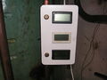 Temperature panel 1.JPG 2,048 × 1,536; 758 KB
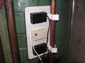 Temperature panel 2.JPG 2,048 × 1,536; 706 KB
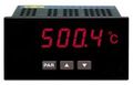 Temperature readout.jpg 180 × 116; 5 KB
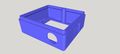 Terminal box.jpg 1,362 × 617; 102 KB
- Terminal box.stl ; 690 KB
 Terminal box lid.jpg 1,362 × 617; 65 KB
- Terminal box lid.stl ; 1.88 MB
 Testimage1.gif 800 × 600; 201 KB
 Testimage2.png 800 × 600; 771 KB
 Th 1stsampleunsettled zpsbe51c872.jpg 120 × 160; 3 KB
 Th 1stwashsettled zps3b367b25.jpg 120 × 160; 5 KB
 The original non glugging pourer.jpg 160 × 120; 4 KB
 Therecklessengineerformula.png 125 × 130; 2 KB
 Thermocouple switch.jpg 800 × 641; 91 KB
 Thermocouples colours.png 400 × 404; 32 KB
 Tin can crucible.jpg 600 × 450; 91 KB
 Tinypic1.png 800 × 639; 75 KB
 Tinypic2.png 800 × 639; 226 KB
 Tinypic3.png 799 × 411; 130 KB
 Tinypic5.png 800 × 640; 189 KB
 Tinypic6.png 800 × 698; 244 KB
 Titraded soap 1.jpg 640 × 480; 103 KB
 Titraded soap 2.jpg 640 × 480; 105 KB
 Titraded soap 3.jpg 480 × 640; 108 KB
 Titration 003.jpg 3,648 × 2,736; 527 KB
 Titration 1.jpg 600 × 650; 50 KB
 Titration 2.jpg 600 × 650; 43 KB
 Titration 3.jpg 600 × 650; 44 KB
 Titration calculator grab.jpg 1,101 × 853; 119 KB
 Titration kit.jpg 600 × 450; 53 KB
 Titration scales.jpg 600 × 545; 58 KB
 Toluol+WVO.1.2.jpg 321 × 378; 88 KB
 Toluol+WVO.2.2.jpg 325 × 380; 102 KB
 Toluol+WVO.3.JPEG 355 × 381; 93 KB
 Toluol+WVO.4.JPEG 307 × 442; 88 KB
 Top skimmer as it lays.jpg 523 × 393; 19 KB
 Top skimmer function test in water 1.jpg 523 × 393; 24 KB
 Tower strainer.jpg 160 × 120; 4 KB
 Tralles hydrometer.jpg 400 × 400; 17 KB
 Trans1.gif 800 × 250; 4 KB
 Trans2.gif 800 × 230; 13 KB
 Trans3.gif 800 × 230; 10 KB
 Tumeric box and solution.jpg 600 × 450; 56 KB
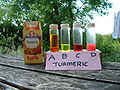 Turmeric.jpg 640 × 480; 98 KB
 Twd.jpg 689 × 429; 44 KB
 Twin misting nozzles.jpg 800 × 600; 32 KB
 Twin misting nozzles 2.jpg 640 × 480; 114 KB
 Two burning glogs.jpg 1,024 × 768; 72 KB
 Two stage process.jpg 640 × 480; 35 KB
 Twyntub150.jpg 288 × 264; 17 KB
 Typical aquarium air pump.jpg 640 × 480; 84 KB
 Typical ceramic airstone.jpg 480 × 640; 85 KB
 UK Cu cylinders.png 800 × 1,061; 120 KB
 Uberderv wood cores1.jpg 600 × 450; 43 KB
 Uberderv wood cores3.jpg 500 × 375; 49 KB
 Universal indicator.jpg 336 × 150; 9 KB
 Untitled-3.jpg 320 × 240; 17 KB
- VW biodiesel ploicy 2010.pdf ; 56 KB
 Valve12v.JPG 640 × 480; 97 KB
 Valve12v2.JPG 640 × 480; 88 KB
 Venturi Formula.jpg 350 × 177; 9 KB
 Venturi cores.jpg 1,843 × 1,134; 605 KB
 Venturi dimensions.gif 600 × 182; 6 KB
 Venturi dimensions 1.gif 600 × 182; 6 KB
 Venturi dimensions 2.gif 600 × 329; 11 KB
 Venturi gclamp.jpg 600 × 450; 80 KB
 Venturi geometry.gif 500 × 207; 3 KB
 Venturi geometry.jpg 500 × 207; 57 KB
 Venturi with drilled throat.jpg 600 × 899; 135 KB
 Venturidimensions.png 500 × 255; 24 KB
 Venturitheory.png 400 × 184; 15 KB
 Vial holder.jpg 1,200 × 1,600; 166 KB
 Vial holder 2.jpg 1,200 × 1,600; 149 KB
 Viscosity cup and timer.jpg 1,024 × 768; 150 KB
 Viscosity cup with hole.jpg 1,024 × 768; 58 KB
- WH7016C instructions.pdf ; 121 KB
 WVO core sample tube Kenr34-infopop.jpg 300 × 400; 13 KB
 WVO core sample tube graphic Kenr34-infopop.jpg 276 × 400; 11 KB
 WVO system 6-5-11 006.jpg 3,648 × 2,736; 731 KB
 WarningIconSmall.png 24 × 24; 1 KB
 Water test 2.jpg 523 × 393; 17 KB
 Water test with full tank.jpg 525 × 395; 17 KB
 Week of chilling 1.JPG 2,560 × 1,920; 954 KB
 Week of chilling 2.JPG 2,560 × 1,920; 1.09 MB
 Week of chilling 3.JPG 2,048 × 1,536; 704 KB
 Week of chilling JP.JPG 2,560 × 1,920; 1.18 MB
 Week of chilling KH.JPG 2,560 × 1,920; 1.19 MB
 Weighing 1 gram of NaOH.jpg 600 × 800; 96 KB
 Weld tube.JPG 2,048 × 1,536; 719 KB
 Weld tube.jpg 2,048 × 1,536; 704 KB
 Welding.JPG 645 × 401; 19 KB
 Weldinglap.JPG 232 × 365; 7 KB
 Wiki creating pages.png 500 × 700; 104 KB
- Wiki graphics master.cdr ; 26 KB
 Wiki graphics master.png 600 × 693; 76 KB
 Wiki login.png 500 × 700; 47 KB
 Wiki logo.png 1,512 × 831; 198 KB
 Wiki logo1.jpg 1,512 × 831; 67 KB
 Wiki upload1.png 800 × 638; 194 KB
 Wiki upload2.png 800 × 640; 136 KB
 Wiki upload3.png 800 × 640; 158 KB
 Wiki upload4.png 800 × 640; 144 KB
 Wiki upload5.png 800 × 640; 255 KB
 Winged jubilee clip 1.JPG 2,048 × 1,536; 719 KB
 Winged jubilee clip 2.JPG 2,048 × 1,536; 746 KB
 Winged jubilee clip kh.jpg 640 × 480; 37 KB
 Winter additives 1.jpg 639 × 479; 45 KB
 Winter additives 2.jpg 639 × 478; 44 KB
 Winter additives 3.jpg 639 × 480; 43 KB
 Wiring6.jpg 639 × 452; 42 KB
 Working view.jpg 521 × 395; 29 KB
 Wrapped filter.JPG 1,536 × 2,048; 674 KB
 Wvo.jpg 640 × 480; 140 KB
 Wvo filtering set up 002.jpg 3,648 × 2,736; 581 KB
 Y Piece 002.jpg 3,648 × 2,736; 1.76 MB
 Yummy.jpg 4,000 × 3,000; 2.8 MB
 Z007p.jpg 666 × 500; 97 KB
 Zeal hydrometer.JPG 2,560 × 1,920; 920 KB


