Uncategorised files
Showing below up to 250 results in range #251 to #500.
View (previous 250 | next 250) (20 | 50 | 100 | 250 | 500)
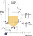
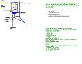
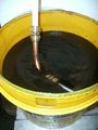
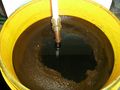
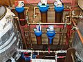
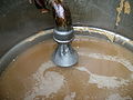
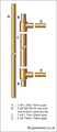
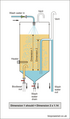 GL wash tank.png 350 × 595; 42 KB
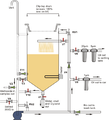
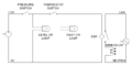
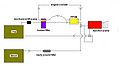
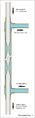
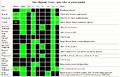 GLstatediagram.JPG 1,101 × 710; 138 KB
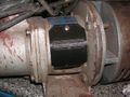
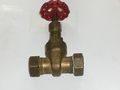 Gate valve.jpg 3,648 × 2,736; 422 KB
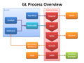
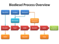 Gl process 01.png 960 × 720; 78 KB
 Gl process 02.png 960 × 720; 108 KB
 Glog - compacting.JPG 2,560 × 1,920; 959 KB
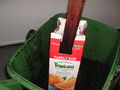
 Glog - tetra-pak taped.JPG 2,560 × 1,920; 860 KB
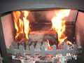 Glog at circa 10 mins.JPG 2,560 × 1,920; 958 KB
 Glog at circa 30 mins.JPG 2,560 × 1,920; 1.02 MB
 Glogs - Stove after fire.JPG 1,024 × 768; 251 KB
 Glogs - ash tray debris.JPG 1,024 × 768; 253 KB
 Glyc log on open fire.jpg 1,024 × 768; 54 KB
 Graham laming.gif 322 × 502; 135 KB
 Gravity filter setup.jpg 2,611 × 1,958; 1.23 MB
 Grille.jpg 1,362 × 617; 179 KB
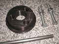
 Ground edge of drum.jpg 600 × 800; 114 KB
 Guage-on-filter.jpg 576 × 432; 38 KB
 Gutter1.JPG 1,536 × 2,048; 598 KB
 Gutter2.JPG 1,536 × 2,048; 664 KB
 HC schematic image map test.png 1,023 × 719; 156 KB
 HMPEheater1.jpg 600 × 450; 74 KB
 HMPEheater10.jpg 600 × 450; 59 KB
 HMPEheater2.jpg 600 × 450; 105 KB
 HMPEheater3.jpg 600 × 450; 110 KB
 HMPEheater4.jpg 600 × 450; 72 KB
 HMPEheater5.jpg 600 × 450; 106 KB
 HMPEheater6.jpg 600 × 450; 73 KB
 HMPEheater7.jpg 600 × 450; 68 KB
 HMPEheater8.jpg 600 × 450; 92 KB
 HMPEheater9.jpg 600 × 450; 70 KB
 HMPEs by Bionoob 1.jpg 1,000 × 750; 655 KB
 HMPEs by Bionoob 2.jpg 1,000 × 750; 613 KB
 HMPEs by Bionoob 3.jpg 1,000 × 750; 639 KB
 HPT1.png 937 × 756; 1.61 MB
 Heat-ring.jpg 349 × 225; 9 KB
 Heat1.JPG 640 × 480; 70 KB
 Heat2.JPG 640 × 480; 83 KB
 Heat3.JPG 640 × 480; 101 KB
 Heat applied flux foams and solidifies.JPG 2,048 × 1,536; 721 KB
 Heater.jpg 3,648 × 2,736; 515 KB
 Heater flange.jpg 500 × 375; 16 KB
 Heater flange and tube.JPG 2,048 × 1,536; 715 KB
 Heatingglycandcaustic.jpg 640 × 480; 135 KB
 Heatsink.jpg 500 × 500; 20 KB
 Hmpe1.jpg 640 × 480; 55 KB
 Hmpe2.jpg 640 × 480; 39 KB
 Hmpe balls.jpg 600 × 450; 54 KB
 Hmpe coil1.jpg 600 × 450; 54 KB
 Hmpe coil2.jpg 600 × 450; 40 KB
 Hmpe settled.jpg 600 × 450; 38 KB
 Home made hydrometer trail jar.JPG 1,920 × 2,560; 920 KB
 Home made hydrometer trail jar base.JPG 800 × 600; 104 KB
 Home made hydrometer trail jar overflow cup.JPG 600 × 800; 60 KB
 Home made hydrometer trail jar readings.JPG 800 × 600; 98 KB
 Home made hydrometer trail jar spout.JPG 800 × 600; 91 KB
 Hozelock-male.jpg 160 × 120; 3 KB
 Hozelock.jpg 3,648 × 2,736; 495 KB
 Hozelock 1.jpg 3,648 × 2,736; 501 KB
 Hozelock 2.jpg 3,648 × 2,736; 505 KB
 Human centrifuge.JPG 1,536 × 2,048; 688 KB
 Hydrometer trial jar.jpg 853 × 1,280; 64 KB
 IDI.gif 500 × 900; 30 KB
 IEC k type plug and socket.jpg 200 × 200; 4 KB
 IMGP0003.jpg 480 × 640; 174 KB
 Immersiuon Flange JRL.jpg 1,024 × 524; 38 KB
 Imploded-reactor-2.jpg 640 × 480; 25 KB
 Imploded-reactor-3.jpg 640 × 480; 34 KB
 Imploded drum.jpg 160 × 120; 15 KB
 In-tank strainer.jpg 640 × 480; 65 KB
 Indirect injection.gif 1,900 × 900; 102 KB
 Inline IP.gif 2,000 × 1,300; 61 KB
 Inline strainer.jpg 640 × 480; 55 KB
 Inside.jpg 3,648 × 2,736; 1.99 MB
 Inside view.JPG 2,048 × 1,536; 725 KB
 Inverted spoon diffuser.png 2,108 × 775; 94 KB
 J-cloth-filters.jpg 666 × 500; 97 KB
 JCloth1 sourceBB.png 399 × 372; 383 KB
 JCloth2 sourceBB.png 578 × 359; 476 KB
 JCloth3 sourceBB.png 726 × 543; 1.01 MB
 JCloth4 sourceBB.png 613 × 329; 423 KB
 JCloth5 sourceBB.png 726 × 543; 1.09 MB
 JCloth6 sourceBB.png 576 × 441; 601 KB
 JP KH comparison 1.JPG 2,048 × 1,536; 721 KB
 JP KH comparison 2.JPG 2,048 × 1,536; 714 KB
 JP KH comparison at 24hrs.JPG 2,048 × 1,536; 706 KB
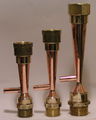 Jamesrl venturis.jpg 822 × 1,024; 109 KB
 Jamesrldiffuser.jpg 874 × 1,024; 71 KB
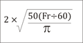 Jamesrlformula.png 250 × 130; 6 KB
 Jamesrlsteelventuris.jpg 783 × 1,024; 64 KB
 Jcloth1 sourceBB.jpg 1,024 × 766; 124 KB
 Jet breaker.jpg 600 × 450; 67 KB
 KGrHqZl4E3HHtTthfBN7lpEGjB0 12.jpg 400 × 400; 20 KB
 KH multi tasking processor 1.png 500 × 592; 61 KB
 KH multi tasking processor 2.png 500 × 592; 55 KB
 KH multi tasking processor 3.png 500 × 592; 53 KB
 KH multi tasking processor draft 3.png 600 × 663; 62 KB
 KH multi tasking processor draft 4.png 600 × 663; 61 KB
 KH multi tasking processor draft 5.png 600 × 663; 74 KB
 KH processor.jpg 640 × 480; 54 KB
 KN water test kit 001.jpg 3,648 × 2,736; 557 KB
 KN water test kit 003.jpg 3,648 × 2,736; 657 KB
 KN water test kit 005.jpg 2,736 × 3,648; 706 KB
 Kh-new-pic.JPG 782 × 817; 50 KB
 Kh.JPG 1,218 × 640; 88 KB
 Kh1.JPG 826 × 640; 51 KB
 Ladle diffuser.jpg 1,024 × 768; 311 KB
 Land Rover 300tdi IP locking tool.png 1,276 × 818; 124 KB
 Land Rover 300tdi IP locking tool photo.JPG 800 × 600; 174 KB
 Land Rover 300tdi flywheel locking tool.png 1,276 × 818; 50 KB
 Land Rover 300tdi flywheel locking tool photo.jpg 800 × 600; 177 KB
 Lap Joint.jpg 390 × 154; 5 KB
 Lavenderandredfooddye.jpg 640 × 480; 66 KB
 Lavenderandsoftsand.jpg 640 × 480; 41 KB
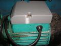
 Leo XKM60.jpg 450 × 350; 19 KB
 Leo XKM60 3 screws.JPG 2,048 × 1,536; 733 KB
 Leo XKM60 alternative puller.JPG 2,048 × 1,536; 732 KB
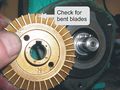 Leo XKM60 bent blade.jpg 2,048 × 1,535; 659 KB
 Leo XKM60 casing seal.JPG 2,048 × 1,536; 730 KB
 Leo XKM60 circlip.JPG 2,048 × 1,536; 742 KB
 Leo XKM60 cover off.JPG 2,048 × 1,536; 752 KB
 Leo XKM60 feeler gauge.JPG 2,048 × 1,536; 744 KB
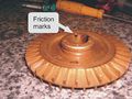 Leo XKM60 friction marks.jpg 2,048 × 1,535; 583 KB
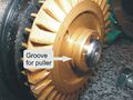 Leo XKM60 groove for puller.jpg 2,048 × 1,535; 527 KB
 Leo XKM60 puller 1.JPG 2,048 × 1,536; 690 KB
 Leo XKM60 puller 2.JPG 2,048 × 1,536; 703 KB
 Leo XKM60 puller in position.JPG 2,048 × 1,536; 743 KB
 Leo XKM60 seal damage.JPG 2,048 × 1,536; 712 KB
 Leo XKM60 static ceramic disc.JPG 2,048 × 1,536; 678 KB
 Leo XKM60 straightening blade.JPG 2,048 × 1,536; 746 KB
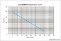 Leo XKM 60 curve.png 650 × 441; 40 KB
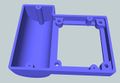
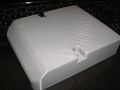 Leo terminal box.JPG 800 × 600; 91 KB
 Leo terminal box.stl ; 1.22 MB
 Leo terminal box bottom.jpg 1,276 × 850; 85 KB
 Leo terminal box fitted.JPG 800 × 600; 113 KB
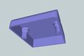
 Leo terminal box top.jpg 1,276 × 850; 69 KB
 Level switch 1.png 480 × 640; 676 KB
 Level switch 2.png 480 × 360; 349 KB
 Level switch 3.png 360 × 480; 360 KB
 Level switch circuit.png 763 × 383; 26 KB
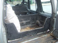 Loadliner.jpg 1,024 × 768; 162 KB
 Log burner glass clean.JPG 2,560 × 1,920; 1,021 KB
 Lowara terminal box - bottom.jpg 1,276 × 882; 163 KB
 Lowara terminal box 1.jpg 1,276 × 850; 103 KB
 Lowara terminal box cover.jpg 1,916 × 938; 186 KB
- Lowara terminal box lower.stl ; 547 KB
- Lowara terminal box upper.stl ; 1.31 MB
 Lugs welded on outside.JPG 2,048 × 1,536; 736 KB
 MS 3rd rebuild 1.jpg 800 × 600; 98 KB
 MS 3rd rebuild 2.JPG 800 × 600; 82 KB
 Measuring equipment.jpg 600 × 450; 47 KB
 Mechanical flange.jpg 500 × 375; 16 KB
 MeltedHDPEprocessor.jpg 320 × 240; 29 KB
 Melting stick 001.jpg 3,648 × 2,736; 1.68 MB
 Melting stick 0013.jpg 3,648 × 2,736; 534 KB
 Melting stick 002.jpg 3,648 × 2,736; 721 KB
 Melting stick 003.jpg 3,648 × 2,736; 511 KB
 Melting stick 005.jpg 2,736 × 3,648; 776 KB
 Melting stick 006.jpg 3,648 × 2,736; 813 KB
 Melting stick 008.jpg 3,648 × 2,736; 432 KB
 Melting stick 1.jpg 3,648 × 2,736; 735 KB
 Melting stick 2.jpg 3,648 × 2,736; 596 KB
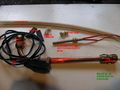
 Melting stick components.jpg 1,041 × 777; 130 KB
 Melting tank with 20l drum.JPG 2,048 × 1,536; 659 KB
 Melting tank with frymax tub.png 450 × 600; 684 KB
 Meth att 002.jpg 1,600 × 1,200; 494 KB
 Meth mixer design 1point1.jpg 600 × 800; 107 KB
 Meth mixer design 1point2.jpg 600 × 800; 83 KB
 Meth mixer design 1point3.jpg 600 × 450; 56 KB
 Meth mixer design 1point4.jpg 600 × 450; 46 KB
 Meth mixer design 1point5.jpg 600 × 450; 44 KB
 Methanol-oil-bio.JPG 2,560 × 1,920; 857 KB
 Methanol-oil-bio and ASM.JPG 2,560 × 1,920; 909 KB
 Methanol SG1.JPG 2,560 × 1,920; 928 KB
 Methanol dispensing.jpg 480 × 640; 89 KB
 Methoxide mixer 01 small.jpg 600 × 986; 276 KB
 Methoxide mixer assembly 01 small.jpg 500 × 738; 44 KB
 Micro HPT.JPG 1,536 × 2,048; 663 KB
 Mini sock 1.jpg 600 × 800; 113 KB
 Mini sock 2.jpg 600 × 800; 91 KB
 Mini sock 3.JPG 600 × 800; 104 KB
 Modified KH processor.jpg 640 × 480; 79 KB
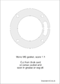
 Mono ML coupling gaurd.png 1,201 × 722; 31 KB
- Mono ML coupling gaurd.stl ; 149 KB
 Mono MM and ML Manual.pdf ; 1.72 MB
 Mono MS cover in fitted.jpg 800 × 600; 176 KB
 Mono MS cover plastic wasted in support.JPG 800 × 600; 151 KB
 Mono MS cover printed VS original.JPG 800 × 600; 132 KB
- Mono MS gasket.pdf ; 1.31 MB
 Mono MS gasket.png 2,491 × 3,484; 295 KB
 Mono MS gaurd.png 1,276 × 850; 74 KB
- Mono MS gaurd.stl ; 308 KB
- Mono MS manual.pdf ; 1.66 MB
 Mono ms1.jpg 225 × 225; 6 KB
 Mono ms10 damaged ceramic.jpg 800 × 600; 117 KB
 Mono ms11 seal fixed half location.jpg 800 × 600; 149 KB
 Mono ms12 lapped seal.jpg 800 × 600; 116 KB
 Mono ms13 seal fixed half chamfer.jpg 800 × 600; 109 KB
 Mono ms2 seal parts and rotor.jpg 800 × 600; 67 KB
 Mono ms3 old and new o ring.JPG 800 × 600; 68 KB
 Mono ms4 thrower ring.JPG 2,560 × 1,920; 911 KB
 Mono ms5 mechanical seal static track.JPG 800 × 600; 128 KB
 Mono ms6 old o ring section.JPG 800 × 600; 73 KB
 Mono ms7 assembled seal.JPG 800 × 600; 70 KB
 Mono ms8 part assembled pump.JPG 800 × 600; 159 KB
 Mono ms9 part assembled pump with stator.JPG 800 × 600; 140 KB
- N2006P PID Installation & Wiring.pdf ; 474 KB
- N2006P PID step by step.pdf ; 311 KB
 NaOH add.jpg 640 × 480; 53 KB
 NaOH measure.jpg 640 × 480; 42 KB
 NaOH scoop.jpg 640 × 480; 34 KB
 NaOH tare empty.jpg 640 × 480; 44 KB
 NaoH burn - e3msb.jpg 320 × 240; 20 KB
 New-main-setup-center.jpg 816 × 612; 141 KB
 New-p.JPG 810 × 444; 27 KB
 New cover on Mono ML.jpg 800 × 600; 160 KB
 Newlypouredsoap.jpg 640 × 480; 147 KB
 Nige pump term box broke.jpg 640 × 480; 75 KB
 Nige pump term box closed.jpg 640 × 480; 102 KB
 Nige pump term box open.jpg 640 × 480; 104 KB
 NigelBs finished venturi.jpg 600 × 450; 69 KB
 NigelBs venturi cores1.jpg 600 × 300; 30 KB
 NigelBs venturi cores2.jpg 600 × 450; 52 KB
 NigelBs venturi cores3.jpg 600 × 410; 47 KB
 No cone drain.png 600 × 465; 17 KB
 No tit calc.png 718 × 734; 29 KB
 Non glugging pourer.jpg 160 × 120; 5 KB
 Nylon tube.jpg 250 × 164; 6 KB
 Oatmealandessence.jpg 640 × 480; 53 KB
- Oil Collect Form v1.xls ; 347 KB
 Oil drying diffuser by KH.jpg 640 × 480; 111 KB
- Oil limit 2500 check7.xls ; 56 KB
 Old and new Mono ML covers.jpg 800 × 600; 138 KB
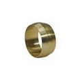 Olive.jpg 140 × 140; 2 KB
 Oxidisation test.jpg 800 × 600; 127 KB
 PD components list.png 250 × 576; 24 KB
 PD cutaway.png 250 × 843; 30 KB
 PD pipe stop.png 250 × 421; 15 KB
 PDclose.JPG 2,048 × 1,536; 689 KB
 PDmachine1.JPG 1,536 × 2,048; 682 KB
 PDmachine2.JPG 2,048 × 1,536; 732 KB
 PDmachine3.JPG 2,048 × 1,536; 729 KB
 PDmachine4.JPG 2,048 × 1,536; 710 KB
 PDmachine5.JPG 1,536 × 2,048; 671 KB
 PDsection.JPG 2,048 × 1,536; 678 KB


