Difference between revisions of "Pump - Tam 105"
| (34 intermediate revisions by 3 users not shown) | |||
| Line 56: | Line 56: | ||
* Max Liquid Viscosity Water | * Max Liquid Viscosity Water | ||
* Ingress Protection IP44 | * Ingress Protection IP44 | ||
| + | * Fuse Rating - 5 Amps | ||
| + | |||
| + | |||
==Spares== | ==Spares== | ||
| Line 62: | Line 65: | ||
Spares for this pump are readily available from the main stockists and distributors whose details can be found on the internet | Spares for this pump are readily available from the main stockists and distributors whose details can be found on the internet | ||
| − | [[File: | + | [[File:Tam105 exploded diagram.jpg]] |
| − | |||
| − | Accessories | + | |
| + | {| class="wikitable" | ||
| + | |- | ||
| + | ! ItemNo. | ||
| + | ! scope="col" width="80"|Part No. | ||
| + | ! scope="col" width="150"|Description | ||
| + | ! scope="col" width="97"| | ||
| + | ! ItemNo. | ||
| + | ! scope="col" width="80"|Part No. | ||
| + | ! scope="col" width="150"|Description | ||
| + | |||
| + | |- | ||
| + | | 1 | ||
| + | | HT10501 | ||
| + | | Screw | ||
| + | | | ||
| + | | 15 | ||
| + | | HT10515 | ||
| + | | Capacitor | ||
| + | |- | ||
| + | | 2 | ||
| + | | HT10502 | ||
| + | | Fill plug | ||
| + | | | ||
| + | | 16 | ||
| + | | HT10516 | ||
| + | | Terminal cover, 16-A Terminal Box | ||
| + | |- | ||
| + | | 3 | ||
| + | | HT10503 | ||
| + | | O ring | ||
| + | | | ||
| + | | 17 | ||
| + | | - | ||
| + | | Not used | ||
| + | |- | ||
| + | | 4 | ||
| + | | HT10504 | ||
| + | | Pump body | ||
| + | | | ||
| + | | 18 | ||
| + | | HT10518 | ||
| + | | Terminal block | ||
| + | |- | ||
| + | | 5 | ||
| + | | HT10505 | ||
| + | | O ring | ||
| + | | | ||
| + | | 19 | ||
| + | | - | ||
| + | | Not used | ||
| + | |- | ||
| + | | 6 | ||
| + | | HT10506 | ||
| + | | Impeller | ||
| + | | | ||
| + | | 20 | ||
| + | | HT10520 | ||
| + | | Stator | ||
| + | |- | ||
| + | | 7 | ||
| + | | HT10507 | ||
| + | | Spring lock | ||
| + | | | ||
| + | | 21 | ||
| + | | HT10521 | ||
| + | | End cover | ||
| + | |- | ||
| + | | 8 | ||
| + | | HT10508 | ||
| + | | Mechanical seal | ||
| + | | | ||
| + | | 22 | ||
| + | | HT10522 | ||
| + | | Fan cover | ||
| + | |- | ||
| + | | 9 | ||
| + | | HT10509 | ||
| + | | Splash guard | ||
| + | | | ||
| + | | 23 | ||
| + | | - | ||
| + | | Not used | ||
| + | |- | ||
| + | | 10 | ||
| + | | HT10510 | ||
| + | | Front cover | ||
| + | | | ||
| + | | 24 | ||
| + | | HT10524 | ||
| + | | Bearing 201 | ||
| + | |- | ||
| + | | 11 | ||
| + | | HT10511 | ||
| + | | Bearing 201 | ||
| + | | | ||
| + | | 25 | ||
| + | | HT10525 | ||
| + | | Spring washer | ||
| + | |- | ||
| + | | 12 | ||
| + | | HT10512 | ||
| + | | Key | ||
| + | | | ||
| + | | 26 | ||
| + | | HT10526 | ||
| + | | Fan | ||
| + | |- | ||
| + | | 13 | ||
| + | | HT10513 | ||
| + | | Rotor | ||
| + | | | ||
| + | | 27 | ||
| + | | HT10527 | ||
| + | | Bolt | ||
| + | |- | ||
| + | | 14 | ||
| + | | HT10514 | ||
| + | | Screw | ||
| + | | | ||
| + | | | ||
| + | | | ||
| + | | | ||
| + | |} | ||
| + | |||
| + | When ordering the plastic terminal connection box, Part-Number HT10516 (part 16 in the parts diagram) Ensure the person taking the order is aware that this comprises of both the top lid as well as the terminal box, or you end up with just the lid. | ||
| + | |||
| + | |||
| + | ==Accessories== | ||
* Foot Valve Filter 7950561 | * Foot Valve Filter 7950561 | ||
| Line 71: | Line 201: | ||
* I.D. Reinforced Hose for Suction and delivery 7955010 | * I.D. Reinforced Hose for Suction and delivery 7955010 | ||
* I.D. Layflat Hose for delivery only 7955110 | * I.D. Layflat Hose for delivery only 7955110 | ||
| − | |||
| + | |||
| + | |||
| + | ==Maintenance== | ||
<gallery caption="Tam 105 impeller replacement" widths="280px" heights="200px" perrow="3" align="center"> | <gallery caption="Tam 105 impeller replacement" widths="280px" heights="200px" perrow="3" align="center"> | ||
| Line 78: | Line 210: | ||
File:Tam 02 Rob-b.jpg|Remove three screws using an 8mm socket. The metal is too soft for a screw driver. Remove the pump body. | File:Tam 02 Rob-b.jpg|Remove three screws using an 8mm socket. The metal is too soft for a screw driver. Remove the pump body. | ||
File:Tam 03 Rob-b.jpg|Damaged impeller with bent/broken vanes. New impellers are available from the original supplier for about £9.00 (price at Jan 2012), part number HT10506. The writer bought two because it's suspected this will happen again. | File:Tam 03 Rob-b.jpg|Damaged impeller with bent/broken vanes. New impellers are available from the original supplier for about £9.00 (price at Jan 2012), part number HT10506. The writer bought two because it's suspected this will happen again. | ||
| − | File:Tam 04 Rob-b.jpg|Before removing the impeller, measure the gap between it and the body with feeler gauges. The central part is not holding the impeller on so gently prise/wiggle the impeller off with a screw driver. Be careful not to | + | File:Tam 04 Rob-b.jpg|Before removing the impeller, measure the gap between it and the body with feeler gauges. The central part is not holding the impeller on so gently prise/wiggle the impeller off with a screw driver. Be careful not to loose the key which can drop out. |
File:Tam 05 Rob-b.jpg|Install the new impeller ensuring the clearance previously measured is maintained and reassemble. | File:Tam 05 Rob-b.jpg|Install the new impeller ensuring the clearance previously measured is maintained and reassemble. | ||
</gallery> | </gallery> | ||
| − | + | ||
[[User:KH|KH]] 19:35, 11 December 2010 (UTC) | [[User:KH|KH]] 19:35, 11 December 2010 (UTC) | ||
Latest revision as of 22:14, 30 November 2014

The TAM 105 1" centrifugal pump is the most popular pump for use in biodiesel processers but remember you are buying a pump that is marketed for clean water only,the figures below only apply to water but are good for comparisons.
TAM 105 specifications
- Motor 230V 50Hz 1ph
- Power 330Watts
- Current 1.4Amps
- Capacitor 8uF 450V
- Speed 2800rpm
- Max. Head 35M
- Max. Lift (Suction) 7M
- Bore Size 1”BSP
- Max. Output 40L/min
- Weight 7.2kg
- Part No. 7230350
External link to Product Manual
Components
- Pump Body Cast Iron (Painted)
- Impellor Case Cast Iron (Painted)
- Impellor Case Seal NBR
- Motor Shaft Seal NBR
- Rotor / Gear / Impellor Brass
- Shaft Key / Nut Stainless Steel
- Motor Shaft Stainless
Performance
- Voltage / Frequency 230v / 50Hz
- kW 0.33
- Amps 1.4
- RPM 2800
- Duty Cycle Continuous
- Bypass Valve Y/N N
- Max Flow 40 lpm @ 0 m head
- Discharge Pressure 3.5 Bar / 50.75 PSI
- Max Suction Lift (Dry) None
- Max Suction Lift (Wet) 7 m
- Inlet Fitting 1" BSP
- Outlet Fitting 1" BSP
- Max Particle Tolerance 100 Micron
- Max Liquid Temp 90 Celcius
- Max Room Temp 40 Celcius
- Thermal Protection Y/N Y
- Max Liquid Viscosity Water
- Ingress Protection IP44
- Fuse Rating - 5 Amps
Spares
Spares for this pump are readily available from the main stockists and distributors whose details can be found on the internet

| ItemNo. | Part No. | Description | ItemNo. | Part No. | Description | |
|---|---|---|---|---|---|---|
| 1 | HT10501 | Screw | 15 | HT10515 | Capacitor | |
| 2 | HT10502 | Fill plug | 16 | HT10516 | Terminal cover, 16-A Terminal Box | |
| 3 | HT10503 | O ring | 17 | - | Not used | |
| 4 | HT10504 | Pump body | 18 | HT10518 | Terminal block | |
| 5 | HT10505 | O ring | 19 | - | Not used | |
| 6 | HT10506 | Impeller | 20 | HT10520 | Stator | |
| 7 | HT10507 | Spring lock | 21 | HT10521 | End cover | |
| 8 | HT10508 | Mechanical seal | 22 | HT10522 | Fan cover | |
| 9 | HT10509 | Splash guard | 23 | - | Not used | |
| 10 | HT10510 | Front cover | 24 | HT10524 | Bearing 201 | |
| 11 | HT10511 | Bearing 201 | 25 | HT10525 | Spring washer | |
| 12 | HT10512 | Key | 26 | HT10526 | Fan | |
| 13 | HT10513 | Rotor | 27 | HT10527 | Bolt | |
| 14 | HT10514 | Screw |
When ordering the plastic terminal connection box, Part-Number HT10516 (part 16 in the parts diagram) Ensure the person taking the order is aware that this comprises of both the top lid as well as the terminal box, or you end up with just the lid.
Accessories
- Foot Valve Filter 7950561
- BSP Spigot Hose Connector 7950210
- I.D. Reinforced Hose for Suction and delivery 7955010
- I.D. Layflat Hose for delivery only 7955110
Maintenance
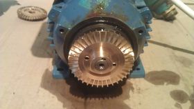
- Tam 105 impeller replacement
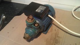
Tam 105 with suspected impeller damage.
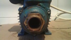
Remove three screws using an 8mm socket. The metal is too soft for a screw driver. Remove the pump body.
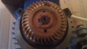
Damaged impeller with bent/broken vanes. New impellers are available from the original supplier for about £9.00 (price at Jan 2012), part number HT10506. The writer bought two because it's suspected this will happen again.
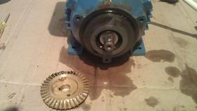
Before removing the impeller, measure the gap between it and the body with feeler gauges. The central part is not holding the impeller on so gently prise/wiggle the impeller off with a screw driver. Be careful not to loose the key which can drop out.
Install the new impeller ensuring the clearance previously measured is maintained and reassemble.


KH 19:35, 11 December 2010 (UTC)