Difference between revisions of "Thermocouples"
| Line 182: | Line 182: | ||
</tr> | </tr> | ||
</table> | </table> | ||
| + | |||
| + | |||
The most widely used combination of conductor materials is Nickel-Chrome and Nickle-Aluminium, known as a type K thermocouple and it is this type that’s best suited to Biodiesel processors. It has a broad range, more than covering the temperatures we work with, is widely available and the thermocouples and accessories are reasonably priced. | The most widely used combination of conductor materials is Nickel-Chrome and Nickle-Aluminium, known as a type K thermocouple and it is this type that’s best suited to Biodiesel processors. It has a broad range, more than covering the temperatures we work with, is widely available and the thermocouples and accessories are reasonably priced. | ||
Revision as of 21:08, 30 July 2011
A thermocouple is a devise which comprises of two conductors made from dissimilar metals these generate a very small voltage known as contact potential. The voltage generated varies with temperature. They are available in a variety of types dependant on conductor material. Each combination of conductor material has a different temperature range and output voltage. Thermocouples are available mounted in various housing to suit specific applications.
Contents
Principles of operation
In the early part of the ninetieth century Thomas Seebeck, an Estonian-born German physicist, discovered that in a circuit made with two dissimilar conductor materials, a voltage would be generated whenever there was a difference in temperature between the two junctions.
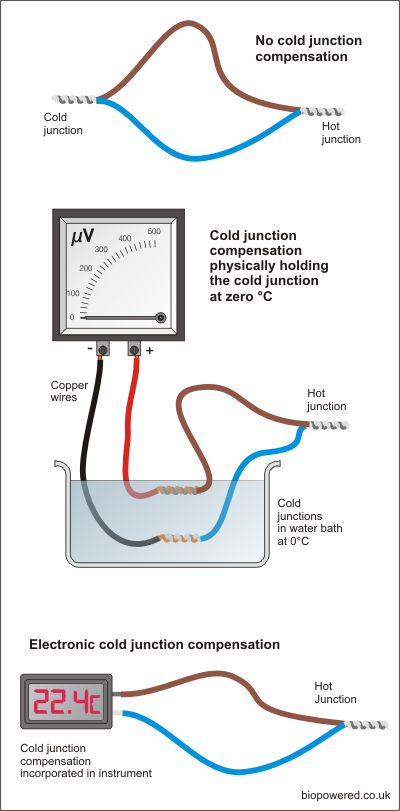
In the top diagram, left, a voltage will be generated if the right-hand junction is heated. The voltage will be proportionate to the temperature, so the hotter the junction the higher the voltage. It’s not quite a linier relationship, but very close. If the voltage were measured and converted to a temperature, the figure arrived at won’t be the actual temperature, it will be the difference in temperature between the hot and the cold junction. So if the cold junction is at an ambient of 22°C and the hot junction at 100°C then the voltage reading will correspond to 78°C.
To make Seedbeck’s discovery more practical, the cold junction needs to be at a know temperature. Looking at the centre diagram, using 0°C as a reference for the cold junction means that the temperature corresponding to the voltage generated by the hot junction will be an absolute measurement.
Rather than having bowls of ice water slopping around all over the place, modern instruments contain electronics to replicate the cold junction which makes life a whole lot less complicated as shown in the lower diagram. Whilst the built in cold junction compensation makes life easer in some respects, it makes it a little more complicated in others. You will notice that the system using the water bath uses copper wires to connect to the volt meter. This is normally bad practice when connecting thermocouples as again you have a junction of dissimilar metals which will also generate a voltage if their temperature differs.
In the centre diagram the use of copper wires is possible because both cold junctions are at the same temperature in the water bath. Where the cold junction compensation is located in the instrument it is necessary to use the same, or very similar, conductor materials for the wiring between the thermocouple and the instrument.
Thermocouple types
Almost any two metals can generate a contact potential, but specific combinations have become standard and are designed to suit different applications.
|
Type |
Conductor materials |
Range
°C |
Output µV/°C |
|
E |
Chromel/Constantan |
0~1000 |
56 |
|
J |
Iron/Constantan |
0~700 |
52 |
|
K |
Chromel/Alumel |
0~1100 |
40 |
|
N |
Nicrosil/Nisil |
0~1100 |
38 |
|
R |
Platinum/PtRh13% |
0~1600 |
10 |
|
S |
Platinum/PtRh10% |
0~1600 |
10 |
|
T |
Copper/Constantan |
-185~300 |
38 |
The most widely used combination of conductor materials is Nickel-Chrome and Nickle-Aluminium, known as a type K thermocouple and it is this type that’s best suited to Biodiesel processors. It has a broad range, more than covering the temperatures we work with, is widely available and the thermocouples and accessories are reasonably priced.
Thermocouple manufacture
Although two wires of dissimilar metals twisted together will work, commercially thermocouple wires are usually fused together by resistance welding.
This can be done quite easily in the home workshop using a car battery. Bare both ends of the pair of wires and twist together. Put one end on one terminal and just flash the other end on the other terminal. Most thermocouple wire is very thin, so you shouldn’t get a massive spark, but bear in mind that lead acid batteries generate Hydrogen so ensure adequate ventilation around the battery top prior to welding.
If the wire is quite thick, it may be safer to hold the twisted end in an oxyacetylene flame if one’s available.
Thermocouples have been made by soldering the two wires together, but with this method you are introducing another dissimilar metal along with possible false readings.
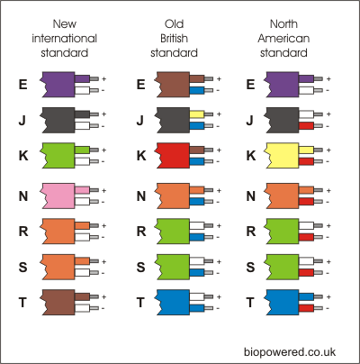
If you do have a go at making your own thermocouple, you need to be aware that thermocouple wire and thermocouple extension wire is available. Thermocouple wire is the only one which will make the correct devise. Thermocouple extension wire is not made of the correct metals. It’s constructed from cheaper metal and is intended to connect the thermocouple to the instrument without introducing errors.
The manufacturing process described above produces what is known as an exposed junction thermocouple. In reality it’s probably quicker and cheaper to buy ready made thermocouples which are available in a variety of housings to suit various applications.

